
Owner manual


MAX6902
SPI-Compatible RTC in a TDFN
_______________________________________________________________________________________ 3
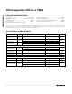
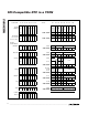
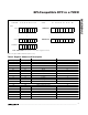
AC ELECTRICAL CHARACTERISTICS
(V
CC
= +2.0V to +5.5V, T
A
= -40°C to +85°C. Typical values are at V
CC
= +3.3V, T
A
= +25°C, unless otherwise noted.) (Figure 5,
Notes 1, 4)
PARAMETER SYMBOL CONDITIONS MIN TYP MAX UNITS
OSCILLATOR
X1 to Ground
Capacitance
25 pF
X2 to Ground
Capacitance
25 pF
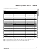
SPI SERIAL TIMING
Maximum Input Rise
Time
t
rIN
DIN, SCLK, CS 2 µs
Maximum Input Fall
Time
t
fIN
DIN, SCLK, CS 2 µs
Output Rise Time t
rOUT
DOUT, C
LOAD
= 100pF 10 ns
Output Fall Time t
fOUT
DOUT, C
LOAD
= 100pF 10 ns
V
CC
= +2V 1000
SCLK Period t
CP
V
CC
= +5V 238
ns
SCLK High Time t
CH
100 ns
SCLK Low Time t
CL
100 ns
SCLK Fall to DOUT
Valid
t
DO
C
LOAD
= 100pF 100 ns
DIN to SCLK Setup
Time
t
DS
100 ns
DIN to SCLK Hold
Time
t
DH
2ns
SCLK Rise to CS
Rise Hold Time
t
CSH
2ns
CS High Pulse Width t
CSW
200 ns
CS High to DOUT
High Impedance
t
CSZ
100 ns
CS to SCLK Setup
Time
t
CSS
100 ns
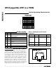
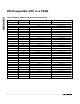
Note 1: All parameters are 100% tested at T
A
= +25°C. Limits over temperature are guaranteed by design and characterization and
not production tested.
Note 2: I
CC
is specified with DOUT open, CS = DIN = GND, SCLK = 4MHz at V
CC
= +5V; SCLK = 1MHz at V
CC
= +2.0V.
Note 3: Timekeeping current is specified with CS = V
CC
, SCLK = DIN = GND, DOUT = 100kΩ to GND.
Note 4: All values referred to V
IH
min and V
IL
max levels.