
Instruction Manual

MAX5945
the bits in register R12h to 00. A high in HWMODE_
switches the port into auto mode by setting the bits in
register R12h to 11. If WD_INT_EN is set, an interrupt is
sent if any of the SMODE bits are set.
A reset sets R1Fh = 00h.
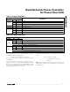
Use IGATE[2:0] (Table 27) to set the gate pin pullup
current, I
PU
, according to the following formula:
I
PU
= 50µA - 6.25 x N
where N is the decimal value of IGATE[2:0].
Use AC_TH[2:0] to program the current threshold of the
AC disconnect comparator according to the following
formula:
IAC_TH = 213.68µA + 28.33µA x N
where N is the decimal value of AC_TH[2:0].
Note: The programmed value has the same percent-
age tolerance as the value specified in the Electrical
Characteristics.
When set low, DET_BYP inhibits port power-on if the
discovery detection was bypassed in AUTO mode.
When set high, it allows the part to turn on power to a
non-IEEE 802.3af load without doing detection. If
OSCF_RS is set high, the OSC_FAIL bit is ignored.
A reset sets R23h = 04h, which sets I
PU
= 50µA and
I
AC_TH
= 325µA as shown in the Electrical
Characteristics.
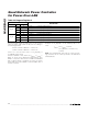
Use R27h (Table 28) to program the current-limit
threshold, V
SU_LIM
, and the nominal load disconnect
detection time, t
DISC
nominal.
Use IMAX[3:0] to program the current-limit trip voltage
according to the following formula:
V
SU_LIM
= 135mV + 19.25mV x N
where N is the decimal value of IMAX[3:0]. The
V
FAULT_LIM
limit scales proportionally to the V
SU_LIM
value (I
FAULT
= 88% of V
SU_LIM
).
A reset sets R27h = 47h, which sets V
SU_LIM
= 212mV
(typical) as shown in the Electrical Characteristics. The
default threshold is set to meet the IEEE 802.3af stan-
dard when using an R
SENSE
= 0.5Ω ±1%, 100ppm.
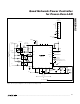
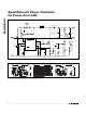
Quad Network Power Controller
for Power-Over-LAN
32 ______________________________________________________________________________________
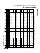
ADDRESS = 1Eh
SYMBOL BIT R/W
DESCRIPTION
7 R/W WDTIME[7]
6 R/W WDTIME[6]
5 R/W WDTIME[5]
4 R/W WDTIME[4]
3 R/W WDTIME[3]
2 R/W WDTIME[2]
1 R/W WDTIME[1]
WDTIME
0 R/W WDTIME[0]
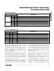
Table 25. Watchdog Timer Register
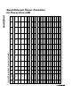
ADDRESS = 1Fh
SYMBOL BIT R/W
DESCRIPTION
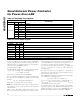
EN_WHDOG 7 R/W A logic high enables the watchdog function
WD_INT_EN 6 — Enables interrupt on SMODE_ bits
Reserved 5 —
Reserved 4 R/W
HWMODE4 3 R/W Port 4 switches to AUTO if logic high and to SHUTDOWN if logic low when watchdog timer expires
HWMODE3 2 R/W Port 3 switches to AUTO if logic high and to SHUTDOWN if logic low when watchdog timer expires
HWMODE2 1 R/W Port 2 switches to AUTO if logic high and to SHUTDOWN if logic low when watchdog timer expires
HWMODE1 0 R/W Port 1 switches to AUTO if logic high and to SHUTDOWN if logic low when watchdog timer expires
Table 26. Switch Mode Register