
Instruction Manual

ther extend the programming range of these timers and
also increase the programming resolution.
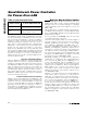
When the MAX5945 shuts down a port due to an
extended overcurrent condition (either during startup or
normal operation), if RSRT_EN is set high, then the part
does not allow the port to power back on before the
restart timer (Table 19a) returns to zero. This effectively
sets a minimum duty cycle that protects the external
MOSFET from overheating during prolonged output
overcurrent conditions.
A reset sets R16h = 00h.
Setting CL_DISC to 1 (Table 20) enables port-over-
class current protection, where the MAX5945 scales
down the overcurrent limit (V
FLT_LIM
) according to the
port classification status. This feature provides protec-
tion to the system against PDs that violate their maxi-
mum class current allowance.
A reset sets R17h = 0xC0.
Power-enable pushbutton (Table 21) for SEMI and
MANUAL modes. Setting PWR_ON_ to 1 turns on
power to the corresponding port. Setting PWR_OFF_ to
1 turns off power to the port. PWR_ON_ is ignored
MAX5945
Quad Network Power Controller
for Power-Over-LAN
______________________________________________________________________________________ 29
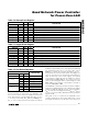
ADDRESS = 15h
SYMBOL BIT R/W
DESCRIPTION
Reserved 7 R Reserved
Reserved 6 R Reserved
Reserved 5 R Reserved
Reserved 4 R Reserved
BCKOFF4 3 R/W Enable Cadence timing on port 4
BCKOFF3 2 R/W Enable Cadence timing on port 3
BCKOFF2 1 R/W Enable Cadence timing on port 2
BCKOFF1 0 R/W Enable Cadence timing on port 1
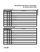
Table 18. Backoff Enable Register
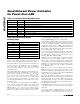
ADDRESS = 16h
SYMBOL BIT R/W
DESCRIPTION
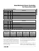
RSTR[1] 7 R/W Restart timer programming bit 1
RSTR[0] 6 R/W Restart timer programming bit 0
TSTART[1] 5 R/W Startup timer programming bit 1
TSTART[0] 4 R/W Startup timer programming bit 0
TFAULT[1] 3 R/W Overcurrent timer programming bit 1
TFAULT[0] 2 R/W Overcurrent timer programming bit 0
TDISC[1] 1 R/W Load disconnect timer programming bit 1
TDISC[0] 0 R/W Load disconnect timer programming bit 0
Table 19. Timing Register
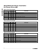
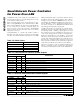
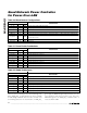
BIT [1:0] RSTR t
DISC
t
START
t
FAULT
00 16 x t
FAULT
t
DISC
nominal
(350ms, typ)
t
START
nominal
(60ms, typ)
t
FAULT
nominal
(60ms, typ)
01 32 x t
FAULT
1/4 x t
DISC
nominal 1/2 x t
START
nominal 1/2 x t
FAULT
nominal
10 64 x t
FAULT
1/2 x t
DISC
nominal 2 x t
START
nominal 2 x t
FAULT
nominal
11 0 x t
FAULT
2 x t
DISC
nominal 4 x t
START
nominal 4 x t
FAULT
nominal
Table 19a. Startup, Fault, and Load Disconnect Timers with Default Values in the
Register 27h and 28h