
Instruction Manual

Software resets of ports (RESET_P_ bit, Table 22) do
not affect the mode register.
Setting DCD_EN_ to 1 enables the DC load disconnect
detection feature (Table 16). Setting ACD_EN_ to 1
enables the AC load disconnect feature. If enabled, the
load disconnect detection starts during power mode
and after startup when the corresponding PGOOD_ bit
in register R10h (Table 13) goes high. A Reset sets
R13h = 0000AAAA where A represents the latched-in
state of the AUTO input prior to the reset.
Setting DET_EN_/CLASS_EN_ to 1 (Table 17) enables
load detection/classification, respectively. Detection
always has priority over classification. To perform clas-
sification without detection, set the DET_EN_ bit low
and CLASS_EN_ bit high.
MAX5945
Quad Network Power Controller
for Power-Over-LAN
______________________________________________________________________________________ 27
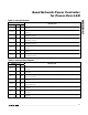
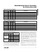
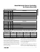
ADDRESS = 10h
SYMBOL BIT R/W
DESCRIPTION
PGOOD4 7 R Power-good condition on port 4
PGOOD3 6 R Power-good condition on port 3
PGOOD2 5 R Power-good condition on port 2
PGOOD1 4 R Power-good condition on port 1
PWR_EN4 3 R Power is enabled on port 4
PWR_EN3 2 R Power is enabled on port 3
PWR_EN2 1 R Power is enabled on port 2
PWR_EN1 0 R Power is enabled on port 1
Table 13. Power Status Register
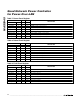
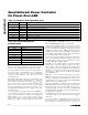
ADDRESS = 11h
SYMBOL BIT R/W
DESCRIPTION
Reserved 7 R Reserved
Reserved 6 R Reserved
A3 5 R Device address, A3 pin latched-in status
A2 4 R Device address, A2 pin latched-in status
A1 3 R Device address, A1 pin latched-in status
A0 2 R Device address, A0 pin latched-in status
MIDSPAN 1 R MIDSPAN input’s latched-in status
AUTO 0 R AUTO input’s latched-in status
Table 14. Address Input Status Register
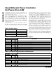
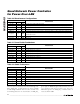
ADDRESS = 12h
SYMBOL BIT R/W
DESCRIPTION
P4_M1 7 R/W M0DE[1] for port 4
P4_M0 6 R/W M0DE[0] for port 4
P3_M1 5 R/W M0DE[1] for port 3
P3_M0 4 R/W M0DE[0] for port 3
P2_M1 3 R/W M0DE[1] for port 2
P2_M0 2 R/W M0DE[0] for port 2
P1_M1 1 R/W M0DE[1] for port 1
P1_M0 0 R/W M0DE[0] for port 1
Table 15. Mode Register