
Manual
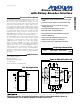

MAX5440
Stereo Volume Control
with Rotary Encoder Interface
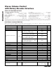
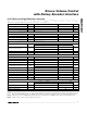
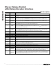
ELECTRICAL CHARACTERISTICS (continued)
(V
DD
= +2.7V to +5.5V, V
SS
= GND = 0, 2.7V ≤ (V
DD
- V
SS
) ≤ 5.5V, V
LOGIC
= +2.7V to V
DD
, V
H_
= V
DD
, V
L_
= V
DD
/ 2, T
A
= T
MIN
to
T
MAX
, unless otherwise specified. Typical values are at T
A
= +25°C.) (Note 1)
PARAMETER SYMBOL CONDITIONS MIN TYP MAX UNITS
Power-Supply Rejection Ratio PSRR
BR
1kHz, 100mV on V
DD
, 1µF on BIAS 60 dB
Maximum Load To V
DD
or GND 3 kΩ
Output Resistance R
OBR
6 Ω
CONTACT INPUTS (MUTE, MODE, RENCODEA, RENCODEB)
Internal Pullup Resistor R
PULLUP
45 kΩ
Single Pulse Input Low Time t
CPW
22 ms
Repetitive Input Pulse Separation t
IPWS
50 ms
Timeout Period t
WS
Click/pop suppression inactive 32 ms
DIGITAL INPUTS (MUTE, MODE, RENCODEA, RENCODEB, SHDN)
3.6V < V
LOGIC
≤ 5.5V 2.4
Input High Voltage (Note 2) V
IH
2.7V ≤ V
LOGIC
≤ 3.6V 2.0
V
3.6V < V
LOGIC
≤ 5.5V 0.8
Input Low Voltage (Note 2) V
IL
2.7V ≤ V
LOGIC
≤ 3.6V 0.6
V
Input Leakage Current Inputs unconnected -1 +1 µA
Input Capacitance 5pF
POWER SUPPLIES
Supply Voltage V
DD
V
SS
= 0 2.7 5.5 V
Negative Power Supply V
SS
V
DD
= +2.7V -2.7 0 V
Supply Voltage Difference V
DD
- V
SS
5.5 V
Active Supply Current I
DD
1.4 mA
V
DD
= +5V, V
SS
= 0 1.3
S tand b y S up p l y C ur r ent ( N otes 3, 4) I
STBY
V
DD
= +2.7V, V
SS
= -2.7V 1.3
µA
Shutdown Supply Current I
SHDN
(Note 3) 1 µA
Power-Up Time t
PU
Click/pop suppression inactive 50 ms
Logic Supply Voltage V
LOGIC
V
SS
= 0 2.7 V
DD
V
Logic Active Supply Current I
L
V
RENCODEA =
V
RENCODEB
= 0V 320 µA
Logic Standby Supply Current I
LSTBY
(Note 4) 1 µA
Logic Shutdown Current I
LSHDN
1µA
LED INDICATORS (LEDIND0–LEDIND4, MODEIND)
V
LOGIC
= 2.7V, I
SINK
= 10mA 0.4
Output Low Voltage V
OL
V
LOGIC
= 5.5V, I
SINK
= 10mA 0.2
V
Output Leakage Current 0.1 10 µA
Output Capacitance 3pF
Maximum Sink Current 150 mA
Note 1: Parameters are 100% production tested at +85°C and limits through temperature are guaranteed by design.
Note 2: The device draws current in excess of the specified supply current when the digital inputs are driven with voltages between
(V
DD
- 0.5V) and (GND + 0.5V). See Digital Supply Current vs. Digital Input Voltage in the Typical Operating Characteristics.
Note 3: Shutdown refers to the SHDN input being asserted low. Standby refers to SHDN not being asserted and all I/O inactive.
Note 4: Supply current measured with the wiper position fixed.
_______________________________________________________________________________________ 3