
Manual

MAX5406
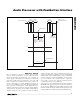
Audio Processor with Pushbutton Interface
20 ______________________________________________________________________________________
When F
L(S)
and F
R(S)
= 2 (LMR, AMBLI, and AMBRI are
connected with the multiplier network of Figure 8), the
equations become:
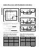
Use a passive filter network as shown in Figure 9 to filter
and delay the LMR signal in more advanced applications.
LOUT L R
ROUT R L
IN IN
IN IN
=
=
3
2
1
2
3
2
1
2
-
-
where
LR
is the signal at LMR
IN IN
-
4
⎛
⎝
⎜
⎞
⎠
⎟
.
LOUT L F
LR
ROUT R F
LR
IN L S
IN IN
IN R S
IN IN
=+ ×
=×
()
()
()
()
-
-
-
4
4
1
0
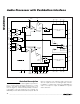
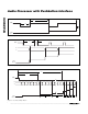
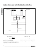
PUSHBUTTON PRESSED
SWITCH
CONTACT
IS BOUNCING
SWITCH
CONTACT
IS STABLE
SWITCH
CONTACT
IS BOUNCING
READY TO ACCEPT
ANOTHER BUTTON PRESS
INPUT ACCEPTED
t
LPW
t
WS
t
HPW
DEBOUNCE BY
WAITING FOR
STABLE LOW, t
IPW
WAIT FOR
FIRST ZERO
CROSSING, t
WS
DEBOUNCE BY
WAITING FOR
STABLE HIGH, t
HPW
WIPER MOTION
WIPER MOVES HERE
Figure 11b. Wiper Transition Timing Diagram (Zero Crossing Detected)