
Manual

MAX5406
Audio Processor with Pushbutton Interface
18 ______________________________________________________________________________________
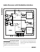
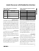
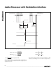
Alternatively, the following formulas can be used to cal-
culate and design for the bass and treble turn-
over frequencies:
where R
B
is nominally 40kΩ (see Figure 7).
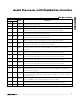
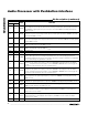
Tables 3 and 4 show the effects of the external bass and
treble capacitance on the maximum output attentuation.
f
RR C
TREBLE TURNOVER
TB T
()
_
()
=
×+×
1
2π
f
RC
BASS TURNOVER
BB
()
_
=
××
1
2π
-1
+1
+1
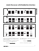
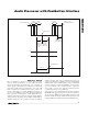
LMR
AMBLI AMBRI
+2
Figure 8. Matrix Surround Configuration
-1
+1
+1
LMR
AMBLI AMBRI
AMBIENCE
NETWORK
Figure 9. Ambience Filter
C
B_1
C
T_1
C
B_2
C
T_2
C
T_
C
B_
C
_SP
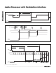
BUFFER
INPUT
TREBLE POT
BASS POT
TO BIAS
40kΩ 116kΩ 40kΩ
3.5kΩ 17kΩ 3.5kΩ
_OUT
Figure 7. Bass/Treble Output Stage
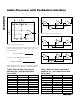
-1
+1
+1
LPR
AMBLI AMBRI
PSEUDOSTEREO
NETWORK
Figure 10. Pseudostereo Filter
C
B_
(nF) CUT (dB) BOOST (dB)
0.00 -11.79 11.81
0.47 -11.25 11.26
1.80 -11.05 11.08
2.20 -10.95 10.96
2.70 -10.85 10.86
3.30 -10.60 10.62
4.70 -10.57 10.55
6.80 -10.10 10.15
8.20 -9.66 9.66
Table 3. Effect of Base Tone Control
Capacitor (C
B
_) on Bass Boost/Bass
Cut at 100Hz
C
T_
(nF) CUT (dB) BOOST (dB)
0.47 -7.80 7.66
1.80 -12.55 12.58
2.20 -12.89 12.95
2.70 -13.15 13.18
3.30 -13.33 13.34
4.70 -13.55 13.58
6.80 -13.59 13.61
8.20 -13.61 13.63
Open -13.79 13.75
Table 4. Effect of Treble Tone Control
Capacitor (C
T
_) on Treble Boost/Treble
Cut at 10kHz