
Manual

MAX5406
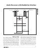
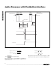
Audio Processor with Pushbutton Interface
______________________________________________________________________________________ 11
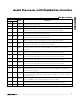
Pin Description
PIN
TSSOP
TQFN
NAME
FUNCTION
143
CBIAS
Bypass Capacitor Connection Point to Internally Generated Bias. Bypass CBIAS with a 50µF
capacitor to system analog ground.
244V
SS
Negative Power-Supply Input. Bypass with a 0.1µF capacitor to system analog ground.
3 45 L1_H
Left-Channel 1 High Terminal Input. Connect the source between L1_H and L1_L for differential
signals. Connect the source to L1_H and tie L1_L to BIAS for single-ended signals.
4 46 L1_L
Left-Channel 1 Low Terminal Input. Connect the source between L1_H and L1_L for differential
signals. Connect L1_L to BIAS for single-ended signals.
5 47 L2_L
Left-Channel 2 Low Terminal Input. Connect the source between L2_H and L2_L for differential
signals. Connect L2_L to BIAS for single-ended signals.
6 48 L2_H
Left-Channel 2 High Terminal Input. Connect the source between L2_H and L2_L for differential
signals. Connect the source to L2_H and tie L2_L to BIAS for single-ended signals.
71LMR
Left Minus Right Output Signal. LMR output provides a signal that is the difference of left and right
input signals. See the Ambience Control section for more details.
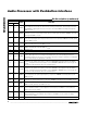
82
AMBLI
Ambience Left-Channel Input. AMBLI provides the proper ambient effect at LOUT based on the
transfer function implemented between LMR and AMBLI. See the Ambience Control section for
more details.
9 3 CTL1
Left-Channel Treble Tone Control Capacitor Terminal 1. Connect a capacitor between CTL1 and
CTL2 to set the treble cutoff frequency. See the Tone Control section for more details.
10 4 CTL2
Left-Channel Treble Tone Control Capacitor Terminal 2. Connect a capacitor between CTL2 and
CTL1 to set the treble cutoff frequency. See the Tone Control section for more details.
11 5 CBL1
Left-Channel Bass Tone Control Capacitor Terminal 1. Connect a capacitor between CBL1 and
CBL2 to set the bass cutoff frequency. See the Tone Control section for more details.
12 6 CBL2
Left-Channel Bass Tone Control Capacitor Terminal 2. Connect a capacitor between CBL2 and
CBL1 to set the bass cutoff frequency. See the Tone Control section for more details.
13 7 LOUT Left-Channel Output
14 8 CLSN
Subwoofer Left-Channel Highpass Filter Capacitor Negative Terminal. Connect a capacitor
between CLSN and CLSP to set the highpass cutoff frequency at SUBOUT. See the Subwoofer
Ouput section for more details.
15 9 CLSP
Subwoofer Left-Channel Highpass Filter Capacitor Positive Terminal. Connect a capacitor between
CLSP and CLSN to set the highpass filter cutoff frequency at SUBOUT. See the Subwoofer Ouput
section for more details.
16 10
SUBOUT
Subwoofer Output. Connect a capacitor from SUBOUT to CSUB to set the lowpass filter cutoff
frequency at SUBOUT. See the Subwoofer Ouput section for more details.
17 11 CSUB
S ub w oofer Low p ass Fi l ter C ap aci tor Ter m i nal . C onnect a fi l ter cap aci tor b etw een C S U B and S U BOU T
to set the l ow p ass fi l ter cutoff fr eq uency. S ee the S ub w oofer Oup ut secti on for m or e d etai l s.
18, 32
12, 26
I.C. Internally Connected. Connect to DGND.