
User guide


MAX5128
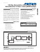
Detailed Description
The MAX5128 nonvolatile, single, linear-taper, digital
potentiometer performs the function of a mechanical
potentiometer or variable resistor, but replaces the
mechanics with a simple 2-wire digital interface. This
device features 128 taps and 22kΩ end-to-end resis-
tance with a 5ppm/°C ratiometric temperature coeffi-
cient. The MAX5128 operates from a +2.7V to +5.25V
power supply and consumes only 0.5µA (typ) of stand-
by supply current. The MAX5128 includes an integrat-
ed nonvolatile memory that recalls the stored wiper
position of the digital potentiometer. A simple 2-wire
up/down interface programs the wiper positions.
Analog Circuitry
The MAX5128 consists of a resistor array with 127
resistive elements; 128 tap points along the resistor
string between H and L are accessible to the wiper, W.
Select the wiper tap point by programming the poten-
tiometer through the 2-wire (UP, DN) interface.
The MAX5128 features power-on reset circuitry that
loads the wiper position from the nonvolatile memory at
power-up.
The nonvolatile memory is programmed to midscale at
the factory.
128-Tap, Nonvolatile, Linear-Taper Digital
Potentiometer in 2mm x 2mm µDFN Package
8 _______________________________________________________________________________________
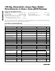
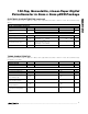
Pin Description
PIN NAME FUNCTION
1V
CC
Power Supply. Bypass V
CC
with a 0.1µF capacitor to GND as close to the device as possible. For proper
operation, limit the supply voltage slew rate to ≥ 10µs.
2H
High Terminal. The voltage at H can be higher than or lower than the voltage at L. Current can flow into or
out of H.
3WWiper Terminal
4L
Low Terminal. The voltage at L can be higher than or lower than the voltage at H. Current can flow into or out
of L.
5 GND Ground
6DNDown Input
7UPUp Input
8 N.C. No Connection. Not internally connected.
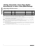
t
PWH
t
PWL
t
PWL
t
PWH
t
MS1
t
MS1
t
WP
t
WS
t
WH
NVM WRITE
UP
DN
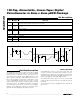
Figure 1. Digital-Interface Timing Diagram