
Instruction Manual

MAX4399
Audio/Video Switch for Three SCART
Connectors
_______________________________________________________________________________________ 9
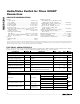
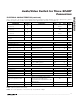
PIN NAME FUNCTION
17 TV_L_IN TV SCART Left-Channel Audio Input
18, 26 G_AUD Audio Ground
19 AUX_L_OUT AUX SCART Left-Channel Audio Output
20 AUX_R_OUT AUX SCART Right-Channel Audio Output
21 VCR_R_OUT VCR SCART Right-Channel Audio Output
23 VCR_L_OUT VCR SCART Left-Channel Audio Output
24 PHONO_R_OUT Hi-Fi Right-Channel Audio Output
25 PHONO_L_OUT Hi-Fi Left-Channel Audio Output
27 RF_MONO_OUT RF Modulator Mono Audio Output
28 TV_L_OUT TV SCART Left-Channel Audio Output
29 TV_R_OUT TV SCART Right-Channel Audio Output
31 V12 +12V Supply. Bypass V12 with a 10µF capacitor in parallel with a 0.1µF capacitor to ground.
32 AUX_SS AUX SCART Bidirectional Slow-Switch Signal
33 TV_SS TV SCART Bidirectional Slow-Switch Signal
34 VCR_SS VCR SCART Bidirectional Slow-Switch Signal
35 TRAP
Trap Filter. Connect a series RLC trap filter to eliminate the color subcarrier frequency
(4.43MHz) from the luma signal. The filter prevents cross-mixing of the color subcarriers when
the luma and chroma signals are added together to form a composite signal. Internally biased
at +0.5V.
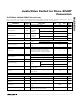
36, 42, 50 G_VID Video Ground
37 TV_FS_OUT
TV SCART Fast-Switching Output. This signal is used to switch the TV to its RGB inputs for on-
screen display purposes.
38, 46, 61 V_VID
Video Supply. Bypass each V_VID with a 0.01µF capacitor to V_GND. Connect a 200nH ferrite
bead from V_VID to a 5V supply.
39 RF_CVBS_OUT RF Modulator Composite Video Output. Internally biased at 1.0V.
40 TV_Y/CVBS_OUT TV SCART Luma/Composite Video Output. Internally biased at 1.0V.
41 TV_R/C_OUT
TV SCART Red/Chroma Video Output. Internally biased at 1.0V for red video signal and 2.1V
for chroma video signal.
43 TV_G_OUT TV SCART Green Video Output. Internally biased at 1.0V.
44 TV_B_OUT TV SCART Blue Video Output. Internally biased at 1.0V.
45 AUX_R/C_OUT
AUX SCART Red/Chroma Video Output. Internally biased at 1.0V for red video signal and 2.1V
for chroma video signal.
47 AUX_Y/CVBS_OUT AUX SCART Luma/Composite Video Output. Internally biased at 1.0V.
48 VCR_Y/CVBS_OUT VCR SCART Luma/Composite Video Output. Internally biased at 1.0V.
49 VCR_R/C_OUT
VCR SCART Red/Chroma Video Output. Internally biased at 1.0V for red video signal and 2.1V
for chroma video signal.
51 VID_BIAS
Video Bias Voltage Output. VID_BIAS sets video bias level for chroma signals. Bypass
VID_BIAS with a low-ESR 0.1µF capacitor to G_VID.
52 TV_R/C_IN TV SCART Red/Chroma Video Input. Internally biased at 1.22V for red, or 1.8V for chroma.
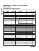
Pin Description (continued)