
Instruction Manual

MAX4399
Audio/Video Switch for Three SCART
Connectors
_______________________________________________________________________________________ 3
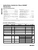
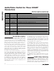
ELECTRICAL CHARACTERISTICS (continued)
(V
V12
= 12V, V
V_VID
= 5V, V
V_DIG
= 5V, 0.47µF X5R capacitor in parallel with a 10µF aluminum electrolytic capacitor from V_AUD to
G_AUD, no load, T
A
= 0°C to +70°C, unless otherwise noted. Typical values are at T
A
= +25°C.) (Note 1)
PARAMETER SYMBOL CONDITIONS MIN TYP MAX UNITS
Slew Rate SR 1V
P-P
input, gain = 6dB 170 V/µs
Gain Matching 1V
P-P
input, between RGB or Y-C -0.5 0 +0.5 dB
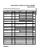
RF_CVBS_OUT 0.03
Differential Gain DG
5-step
modulated
staircase
All other video outputs 0.13
%
RF_CVBS_OUT 0.09
Differential Phase DP
5-step
modulated
staircase
All other video outputs 0.36
degrees
Signal-to-Noise Ratio SNR 1V
P-P
input -86 dB
RF_CVBS_OUT 5
Group Delay
f = 0.1MHz to
6MHz
All other video outputs 3
ns
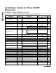
Bottom Level Clamp
RGB, composite and luma, no signal, no
load
1.21 V
Chroma Bias Chroma only, no signal, no load 1.88 V
Sync Crush
Percentage reduction in sync pulse
(0.3V
P-P
); inferred from input clamping
current with a 0.1µF coupling capacitor
-2 0 +2 %
Power-Supply Rejection Ratio PSRR f = 100kHz, 0.5V
P-P
60 dB
CVBS, Y, or RGB video input 4 MΩ
Input Impedance
Chroma video input 11 kΩ
Input Clamp Current V
IN
= 1.75V 2.5 4.2 8.0 µA
RGB, composite, and
luma
1.05
Output Bias Voltage
No signal, no
load
Chroma 2.24
V
Pulldown Resistance
VCR_R/C_OUT, AUX_R/C_OUT,
TV_R/C_OUT
10 Ω
Crosstalk
f = 4.43MHz, 1V
P-P
input, between any two
active inputs
-63 dB
Mute Suppression f = 4.43MHz, 1V
P-P
input, on one input -65 dB
AUDIO
V_AUD Voltage Generated by internal linear regulator 8.1 V
Voltage Gain 1.414V
P-P
input, gain = 0dB -0.25 0 +0.25 dB
Gain Matching Between
Channels
1.414V
P-P
input, gain = 0dB -0.5 0 +0.5 dB
Gain Flatness
f = 20Hz to 20kHz, 0.5V
RMS
input, gain =
0dB
0.005 dB
Frequency Bandwidth
0.5V
RMS
input; frequency where output is
-3dB with 1kHz serving as 0dB
210 kHz