
Instruction Manual
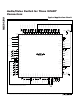

MAX4399
Audio/Video Switch for Three SCART
Connectors
26 ______________________________________________________________________________________
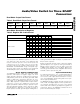
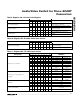
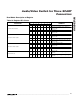
Table 12. Register 07h: TV Video Output Control
BIT
DESCRIPTION
76543210
COMMENTS
—————— 00
Low (<2V) internal source (power-on
default)
—————— 01
Medium (4.5V to 7V). External SCART
source with 16:9 aspect ratio.
—————— 1 0 High impedance
Set TV Slow Switching
—————— 11
High (>9.5V). External SCART source
with 4:3 aspect ratio.
————— 0 ——
Normal operation. Pulldown on
TV_R/C_OUT is off (power-on default).
TV_R/C_OUT Ground
————— 1 ——
Ground. Pulldown on TV_R/C_OUT is
on. The output amplifier driving
TV_R/C_OUT turns off.
——— 00———0 (power-on default)
——— 01———Same level as ENC_FS_IN
——— 10———Same level as VCR_FS_IN
Fast Switching
——— 11———V_VID
—— 0 —————
Composite video from the Y/C mixer is
output
TV_Y/CVBS_OUT Switch
—— 1 —————
The TV_Y/CVBS_OUT signal selected in
register 06h is output (power-on default)
— 0 —————
Composite video from the Y/C mixer is
output (power-on default)
RF_CVBS_OUT Switch
— 1 —————
The TV_Y/CVBS_OUT signal selected in
register 06h is output
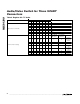
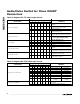
Table 13. Register 08h: VCR Video Input Control
BIT
DESCRIPTION
76543210
COMMENTS
————————VCR_Y/CVBS_OUT VCR_R/C_OUT
————— 0 0 0 ENC_Y/CVBS_IN ENC_R/C_IN
————— 0 0 1 ENC_Y_IN ENC_C_IN
————— 0 1 0 VCR_Y/CVBS_IN VCR_R/C_IN
————— 0 1 1 AUX_Y/CVBS_IN AUX_R/C_IN
————— 1 0 0 TV_Y/CVBS_IN TV_R/C_IN
————— 1 0 1 Mute Mute
————— 1 1 0 Mute Mute
Input Sources for VCR Video
————— 111
Mute (power-on
default)
Mute (power-on
default)
0 ———————
DC restore clamp active at input (power-
on default)
VCR_R/C_IN Clamp/Bias
1 ———————Chroma bias applied at input