
Instruction Manual

MAX4399
2-Wire Interface Slave Address
Programming
Connect DEV_ADDR to G_DIG or V_DIG to set the
MAX4399 write and read addresses as shown in Table 2.
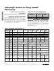
Data Register Writing and Reading
Program the SCART video and audio switches by writ-
ing to registers 00h through 0Dh (Tables 3 through 18).
Registers 00h through 0Dh can also be read, allowing
read-back of data after programming and facilitating
system debugging. The status register is read-only and
can be read from address 0Eh (Table 19).
Applications Information
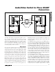
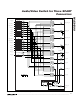
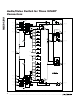
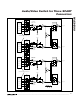
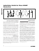
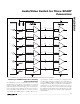
Filtering of Encoder Outputs
The DAC outputs of encoder chips need to be
processed through a lowpass filter (reconstruction filter)
to attenuate out-of-band noise. Figure 9 shows how the
MAX7440 provides an integrated, convenient solution for
reconstruction filtering.
Audio/Video Switch for Three SCART
Connectors
18 ______________________________________________________________________________________
DEV_ADDR
CONNECTION
WRITE
ADDRESS
READ
ADDRESS
G_DIG 94h 95h
V_DIG 96h 97h
Table 2. Slave Address Programming
REGISTER
ADDRESS
POR
VALUE
BIT 7 BIT 6 BIT 5 BIT 4 BIT 3 BIT 2 BIT 1 BIT 0
00h 47h Not used ZCD Volume control
TV audio
mute
01h 07h Not used Not used TV mono switch TV audio selection
02h 07h VCR volume control VCR mono switch VCR audio selection
03h 07h AUX volume control AUX mono switch AUX audio selection
04h 01h Not used Not used Not used Not used
Interrupt
enable
TV volume
bypass
Phono
volume
bypass
Not used
05h 00h
ENC_R/C_IN
Clamp
Not used Not used Not used Not used Not used Not used Not used
06h 1Fh
TV_R/C_IN
clamp
RGB gain
TV G and B video
switch
TV video switch
07h 20h Not used
RF_CVBS_OUT
switch
TV_Y/CVBS_
OUT switch
TV fast switch
TV_R/C_OUT
ground
Set TV slow switch
08h 07h
VCR_R/C_IN
clamp
Not used Not used Not used Not used VCR video switch
09h 00h Not used Not used Not used Not used Not used
VCR_R/C_
OUT
ground
Set VCR slow switch
0Ah 07h
AUX_R/C_IN
clamp
Not used Not used Not used Not used AUX video switch
0Bh 00h Not used Not used Not used Not used Not used
AUX_R/C_
OUT ground
Set AUX slow switch
0Ch 00h Not used Not used Not used Not used Not used Not used
V C R_Y /
C V BS _
OU T
enab l e
VCR_R/
C_OUT
enable
0Dh 00h
AUX_Y/CVBS_
OUT
enable
AUX_R/C_OUT
enable
TV_R/C_OUT
enable
TV_G_OUT
enable
TV_B_OUT
enable
TV_Y/CVBS_
OUT enable
TV_FB_
OUT
enable
RF_CVBS_
OUT
enable
Table 3. Write Mode Input Data Format