
Manual

Detailed Description
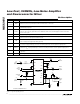
The MAX2685 consists of five major components: a
low-noise amplifier (LNA), an LNA bypass switch, a
downconverter mixer, a local-oscillator (LO) buffer, and
a power-management block.
Low-Noise Amplifier (LNA)
The LNA is a wideband, single-ended cascode amplifi-
er that operates over a wide range of frequencies. The
input of the LNA (LNAIN) requires an appropriate
matching network and a DC-blocking capacitor. The
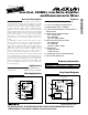
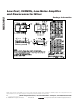
typical operating circuit shown in Figure 1 is optimized
for frequencies around 880MHz, requiring only a 0.1µF
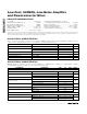
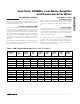
capacitor in series with a 12nH inductor. See Table 1
for the LNA “S” parameters for matching to other fre-
quencies.
The output of the LNA (LNAOUT) is internally biased to
V
CC
. It is internally matched to 50Ω and incorporates
an internal DC-blocking capacitor.
LNA Bypass Switch
and Gain Control
When a large input signal is present, enable the LNA
bypass function to increase linearity and reduce supply
current. Set GAIN low to enable the LNA bypass func-
tion.
Receive Mixer
The downconverter mixer is a wideband, single-bal-
anced design with a low noise figure and high linearity.
The RF signal at the MIXIN port is mixed with the signal
at the LO port, and is downconverted to an IF frequen-
cy at the differential IF port.
RF Input
The MIXIN input requires a simple external matching
network and a series DC-blocking capacitor. See
Figure 1 for a matching network example, optimized for
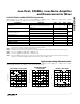
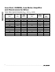
880MHz operation. Table 2 lists mixer “S” parameters
for matching to other frequencies.
MAX2685
Low-Cost, 900MHz, Low-Noise Amplifier
and Downconverter Mixer
_______________________________________________________________________________________ 7
Table 1. LNA Typical S-Parameters (V
CC
= +3V, T
A
= +25°C)
|
S11
|
MAG
FREQUENCY
(MHz)
800 0.761
S11
PHASE
(degrees)
-64.5
|
S21
|
MAG
S21
PHASE
(degrees)
177.94.98
|
S12
|
MAG
S12
PHASE
(degrees)
-163.7
|
S22
|
MAG
S22
PHASE
(degrees)
-107.30.3760.018
-68.6 167.25.06 -167.1840 0.753 -107.00.2640.022
-73.2 156.65.07 -171.3880 0.747 -94.60.1720.026
-78.0 146.64.91 -175.7920 0.733 -62.90.1490.030
-82.8 137.74.68 178.0960 0.719 -42.40.2000.035
-87.5 130.34.40 171.01000 0.693 -38.80.2630.039
-45.6 73.00.188 71.9800 0.625 -91.30.4830.191
-48.1 65.50.195 64.2840 0.621 -91.30.4230.198
-50.9 58.10.199 56.7880 0.619 -89.90.3700.201
-53.3 51.60.200 50.3920 0.611 -86.10.3370.202
-55.5 46.10.200 44.7960 0.608 -80.90.3220.201
-57.5 41.20.200 40.01000 0.607 -76.70.3170.200
High-Gain Mode (GAIN = V
CC
)
Low-Gain Mode (GAIN = GND)