
Manual


MAX2683/MAX2684
3.5GHz Downconverter Mixers
with Selectable LO Doubler
14 ______________________________________________________________________________________
the LOX1 port. Disabling the LO doubler has the bene-
fit of reducing the supply current by 15mA. See Tables
2 and 3 for the LO input frequency ranges.
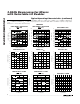
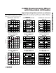
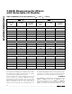
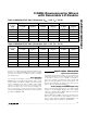
LOX1 and LOX2 are single-ended LO inputs that
achieve a return loss of typically -20dB over the speci-
fied LO input frequency range. They are internally
biased and require a DC-blocking capacitor. To
improve LOX2 input return loss, use a series inductor
between the blocking capacitor and LOX2 input. See
the Typical Operating Circuit for recommended compo-
nent values. See Tables 2 and 3 for LOX1 and LOX2
S-parameters. Leave the unused port unconnected.
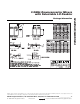
IF Output
The MAX2683 is optimized for IF frequencies in the
100MHz to 400MHz range, while the MAX2684 is opti-
mized for IF frequencies in the 900MHz to 1000MHz
range. The differential, open-collector IFOUT- and
IFOUT+ ports require external pull-up inductors to V
CC
,
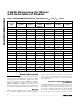
1400 0.210 -72.4 2800 0.305 -158.8
1450 0.209
LOX1
(ENX2 = V
CC
)
LOX1
FREQUENCY
(MHz)
S11 MAG
S11 PHASE
(degrees)
2700 0.296 -152.1
2600 0.281 -147.5
2500 0.266 -143.5
2400 0.249 -138.9
LOX2
(ENX2 = GND)
LOX2
FREQUENCY
(MHz)
S11 MAG
S11 PHASE
(degrees)
1350 0.212 -69.1
1300 0.215 -66.0
1250 0.219 -62.8
1200 0.225 -59.6
-75.4 2900 0.302 -167.3
1200 0.228 -64.7 2400 0.235 -135.3
1250 0.222 -68.9 2500 0.251 -139.8
1300 0.219 -71.2 2600 0.265 -143.5
1350 0.216 -74.4 2700 0.280 -147.8
1400 0.214 -77.8 2800 0.290 -152.8
1450 0.213 -81.0 2900 0.292 -157.0
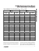
1200 0.212 -75.4 2400 0.224 -132.3
1250 0.222 -63.1 2500 0.240 -136.6
1300 0.217 -66.2 2600 0.255 -140.1
1350 0.213 -69.2 2700 0.269 -143.8
1400 0.211 -72.3 2800 0.279 -147.6
1450 0.209 -75.3 2900 0.283 -150.3
R
BIAS
= 820Ω
R
BIAS
= 1.2kΩ
R
BIAS
= 2.0kΩ
Table 3. MAX2684 LO Port S-Parameters (V
CC
= +5V, T
A
= +25°C)