
Instruction Manual

MAX2203
RMS Power Detector
Maxim cannot assume responsibility for use of any circuitry other than circuitry entirely embodied in a Maxim product. No circuit patent licenses are
implied. Maxim reserves the right to change the circuitry and specifications without notice at any time.
Maxim Integrated Products, 120 San Gabriel Drive, Sunnyvale, CA 94086 408-737-7600 _____________________
7
© 2009 Maxim Integrated Products Maxim is a registered trademark of Maxim Integrated Products, Inc.
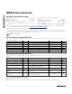
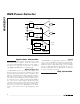
C1
V
CC
V
CC
+
A1
RFIN/
ENA
RF INPUT FROM
DIRECTIONAL
COUPLER
ENABLE
LOGIC INPUT
B1
GND
C2
OUT
TO ADC
C2
4700pF
220pF
C1
0.1µF
MUST BE X5R
OR X7R TYPE
10kΩ
24.3kΩ
50Ω
1%
B2
FILT
A2
GND
TERMINATION RESISTOR NOT NEEDED
IF TWO OR MORE DIRECTIONAL COUPLERS
ARE USED AND CONFIGURED AS IN FIGURE 1.
0.1µF
MAX2203
Typical Operating Circuit
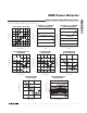
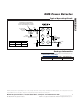
Package Information
For the latest package outline information and land patterns, go
to www.maxim-ic.com/packages
.
PACKAGE TYPE PACKAGE CODE DOCUMENT NO.
6 WLP W61B1+1
21-0217
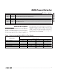
TYPE C1 (µF) C2 (nF)
WCDMA 0.1 4.7
NCDMA 0.33 15