
User Manual


MAX2102/MAX2105
Direct-Conversion Tuner ICs for
Digital DBS Applications
_______________________________________________________________________________________ 5
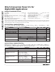
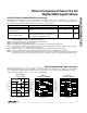
AC ELECTRICAL CHARACTERISTICS (continued)
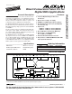
(MAX2102 EV kit circuit (Figure 1); V
CC
= +5V; PSGND = open; MOD = GND; f
RFIN
= 2150MHz; P
RFIN
= -19dBm; f
LO
=
2150.125MHz; P
LO
= -15dBm driven single-ended into LO; AGC set via servo loop for V
IOUT
= V
QOUT
= 0.5Vp-p; IOUT, QOUT drive
AC-coupled 100Ω loads; 2kΩ from PSOUT to GND; T
A
= +25°C; unless otherwise noted.)
(Note 3)
(Note 3)
V
CC
= 5V + 50mVp-p at 300kHz. Amplitude of
300kHz relative to 500mVp-p measured at IOUT,
QOUT. Measured using MAX2102 EV kit.
CONDITIONS
Ω4.7 10IOUT, QOUT Output Impedance
Ω±1
Maximum IOUT to QOUT Output
Impedance Difference
dB32
Power-Supply Ripple Rejection
(measured at IOUT, QOUT)
UNITSMIN TYP MAXPARAMETER
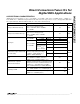
Note 1: All specifications with guaranteed min/max limits are met within this frequency range. Contact factory for
MAX2102/MAX2105 versions with expanded frequency range.
Note 2: Guaranteed by production test and/or design and characterization.
Note 3: Guaranteed by design and characterization.
Note 4: IOUT, QOUT Phase and Amplitude Imbalance specifications are met within this LO power range.
Note 5: Tested under two conditions: 1) Normal test: P
RFIN
= -20dBm, and 2) Overdrive test: P
RFIN
= -5dBm but AGC set via servo
loop for V
IOUT
= V
QOUT
= 0.5Vp-p for P
RFIN
= -30dBm.
Note 6: Negative numbers (-0.1°) indicate improvement in quadrature accuracy with increasing temperature.
Note 7: Includes contribution from front-end gain tilt and delay variations produced by varying f
RFIN
by ±30MHz.
Note 8: 1kHz minimum frequency determined by 0.22µF offset-correction capacitors. Different value capacitors yield proportionally
different low-frequency cutoffs. Group delay at low frequencies will also be affected. See
Applications Information
section.
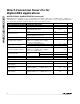
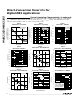
__________________________________________Typical Operating Characteristics
(MAX2102 EV kit circuit (Figure 1), V
CC
= 5V, PSGND = open, MOD = GND, f
RFIN
= 2150MHz, P
RFIN
= -19dBm, f
LO
= 2150.125MHz,
P
LO
= -15dBm driven single-ended into LO, AGC set via servo loop for V
IOUT
= V
QOUT
= 0.5Vp-p, IOUT, QOUT drive AC-coupled
100Ω loads, 2kΩ from PSOUT to GND, T
A
= +25°C, unless otherwise noted.)
120
130
140
150
160
170
180
4.75 4.85 5.00 5.15 5.25
SUPPLY CURRENT
vs. SUPPLY VOLTAGE
MAX2102/05-01
SUPPLY VOLTAGE (V)
SUPPLY CURRENT (mA)
T
A
= 0°C
T
A
= +70°C
PSGND = GND
(PRESCALER ENABLED)
T
A
= +25°C
-80
-60
-70
-40
-50
-30
-20
-10
0
0.8 1.2 1.41.0 1.6 1.8 2.0 2.2
MAX2102
AGC RANGE vs. FREQUENCY
MAX2102/05-02
RFIN FREQUENCY (GHz)
SINGLE-CARRIER POWER FOR 0.5Vp-p
BASEBAND LEVEL (dBm)
T
A
= +70°C
T
A
= +25°C
T
A
= 0°C
T
A
= +70°C
T
A
= +25°C
T
A
= 0°C
AGC = 4V
AGC RANGE
AGC = 1V
-80
-50
-60
-70
-40
-30
-10
-20
0
0.8 1.0 1.2 1.4 1.6
1.8
2.0 2.2
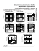
MAX2105
AGC RANGE vs. FREQUENCY
MAX2102/05-01insert
RFIN FREQUENCY (GHz)
SINGLE CARRIER POWER FOR 0.5Vp-p
BASEBAND LEVEL (dBm)
T
A
= 0°C
AGC = 1V
AGC = 4V
T
A
= 0°C
T
A
= +25°C
T
A
= +70°C
T
A
= +70°C
T
A
= +25°C