
User Manual


MAX2102/MAX2105
Direct-Conversion Tuner ICs for
Digital DBS Applications
______________________________________________________________________________________ 11
R
S
BASEBAND LP FILTERS
(OPTIONAL
GAIN)
DSP:
QPSK
DEMOD
0.1µF0.1µF
R
L
L1
L2 L3
OR
C1
C2 C3 C4
0
90
ADC
ADC
AGC
MAX1002
MAX1003
R
S
IDC QDCIDC
LO
AGC
IOUT
QOUT
DIV
RFIN
RFIN
EXTERNAL
VCO
LO
OFFSET CORRECTION
OR
QDC PSOUT
TANK
TSA5055
OR EQUIV.
MOD
0.1µF0.1µF
R
L
L1
L2 L3
C1
C2 C3 C4
KU BAND
75Ω CABLE
950MHz to 2150MHz
F-CONNECTOR
INPUT
F-CONNECTOR
FOR 2nd SET-TOP BOX
LNB
MAX2102
MAX2105
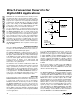
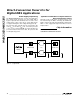
Figure 2. Typical Application
The quadrature downconverter follows the front-end
AGC. Two mixers are driven by the previous stage
AGC amplifier output. The mixer LO ports are fed with
the two LO signals, which are 90° apart in phase.
These quadrature LO signals are generated on-chip
using the LO signal from the LO buffer.
The resulting I/Q baseband signals are fed through
separate I and Q channel baseband amplifiers. Robust
output stages drive IOUT and QOUT. The outputs are
capable of driving lowpass filters with 100Ω character-
istic impedance (that is, the equivalent of an AC-cou-
pled, 100Ω load). The baseband -3dB output band-
width is over 90MHz.
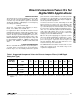
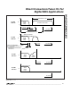
__________Applications Information
Front-End Tuner Circuitry
for DBS Tuners
In a typical application, the signal path ahead of the
MAX2102/MAX2105 will include a discrete LNA/buffer
and a PIN-diode attenuator. Alternatively, a dual-gate