
Instruction Manual


MAX2036
Ultrasound VGA Integrated
with CW Octal Mixer
______________________________________________________________________________________ 13
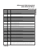
PIN NAME FUNCTION
76 LO1 CW LO Input for Channel 1. LO clock input for modes 3 and 4.
77
VGOUT1+
VGA Channel 1 Noninverting Differential Output
78
VGOUT1-
VGA Channel 1 Inverting Differential Output
80 DIN Serial Port Data Input. Data input to program the serial shift registers.
83 CLK Serial Port Data Clock. Clock input for programming the serial shift registers.
84 CW_M1
CW Mode Select Input 1. Input for programming beamforming mode 1, 2, 3, or 4. See Table 1 for
mode programming details.
85 CW_M2
CW Mode Select Input 2. Input for programming beamforming mode 1, 2, 3, or 4. See Table 1 for
mode programming details.
86
VG_CLAMP_
MODE
VGA Clamp Mode Enable. Drive VG_CLAMP_MODE high to enable high VGA clamp mode. VGA
output is clamped at typically 2.4V
P-P
differential. Drive VG_CLAMP_MODE low to enable low VGA
clamp mode. VGA output is clamped at typically 2.8V
P-P
differential.
88 LOAD
Serial Port Load. Loads the data from the serial shift registers into the I/Q phase dividers. Pull LOAD
bus from high to low, and from low to high for programming the I/Q phase dividers.
89
CW_QOUT+
CW Mixer Noninverting Differential Quadrature Output. CW Mixer output for 8 quadrature mixers
combined.
90
CW_QOUT-
CW Mixer Inverting Differential Quadrature Output. CW Mixer output for 8 quadrature mixers
combined.
91
CW_IOUT-
CW Mixer Inverting Differential In-Phase Output. CW mixer output for 8 in-phase mixers combined.
92
CW_IOUT+
C W M i xer N oni nver ti ng D i ffer enti al In- P hase O utp ut. C W M i xer outp ut for 8 i n- p hase m i xer s com b i ned .
94 VGIN1- VGA Channel 1 Inverting Differential Input
95 VGIN1+ VGA Channel 1 Noninverting Differential Input
97 CWIN1- CW Mixer Channel 1 Inverting Differential Input
98 CWIN1+ CW Mixer Channel 1 Noninverting Differential Input
99 VGIN2- VGA Channel 2 Inverting Differential Input
100 VGIN2+ VGA Channel 2 Noninverting Differential Input
—EP
Exposed Pad. Internally connected to GND. Connect EP to a large PCB ground plane to maximize
thermal performance.
Pin Description (continued)