
Instruction Manual


MAX2036
Ultrasound VGA Integrated
with CW Octal Mixer
______________________________________________________________________________________ 11
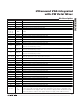
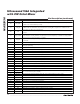
Pin Description
PIN NAME FUNCTION
1 CWIN2- CW Mixer Channel 2 Inverting Differential Input
2 CWIN2+ CW Mixer Channel 2 Noninverting Differential Input
3 VGIN3- VGA Channel 3 Inverting Differential Input
4 VGIN3+ VGA Channel 3 Noninverting Differential Input
5, 10, 19, 24,
29, 34, 58,
79, 81, 96
GND Ground
6 CWIN3- CW Mixer Channel 3 Inverting Differential Input
7 CWIN3+ CW Mixer Channel 3 Noninverting Differential Input
8 VGIN4- VGA Channel 4 Inverting Differential Input
9 VGIN4+ VGA Channel 4 Noninverting Differential Input
11 CWIN4- CW Mixer Channel 4 Inverting Differential Input
12 CWIN4+ CW Mixer Channel 4 Noninverting Differential Input
13 EXT_C1
External Compensation. Connect a 4.7μF capacitor to ground as close as possible to the pin to
bypass the internal biasing circuitry.
14 EXT_C2
External Compensation. Connect a 4.7μF capacitor to ground as close as possible to the pin to
bypass the internal biasing circuitry.
15 EXT_C3
External Compensation. Connect a 4.7μF capacitor to ground as close as possible to the pin to
bypass the internal biasing circuitry.
16, 42, 46,
54, 72, 82, 87
V
CC
5V Power Supply. Connect to an external +5V power supply. Bypass each V
CC
supply to ground
with 0.1μF capacitors as close as possible to the pins.
17 VGIN5- VGA Channel 5 Inverting Differential Input
18 VGIN5+ VGA Channel 5 Noninverting Differential Input
20 CWIN5- CW Mixer Channel 5 Inverting Differential Input
21 CWIN5+ CW Mixer Channel 5 Noninverting Differential Input
22 VGIN6- VGA Channel 6 Inverting Differential Input
23 VGIN6+ VGA Channel 6 Noninverting Differential Input
25 CWIN6- CW Mixer Channel 6 Inverting Differential Input
26 CWIN6+ CW Mixer Channel 6 Noninverting Differential Input
27 VGIN7- VGA Channel 7 Inverting Differential Input
28 VGIN7+ VGA Channel 7 Noninverting Differential Input
30 CWIN7- CW Mixer Channel 7 Inverting Differential Input
31 CWIN7+ CW Mixer Channel 7 Noninverting Differential Input
32 VGIN8- VGA Channel 8 Inverting Differential Input
33 VGIN8+ VGA Channel 8 Noninverting Differential Input
35 CWIN8- CW Mixer Channel 8 Inverting Differential Input
36 CWIN8+ CW Mixer Channel 8 Noninverting Differential Input
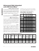
37, 93 V
REF
5V Reference Supply. Connect to a low-noise power supply. Bypass to GND with a 0.1μF capacitor
as close as possible to the pins. Note that noise performance of the device is dependent on the
noise contribution from the supply to V
REF
. Use a low-noise supply for V
REF
. V
CC
and V
REF
can be
connected together to share the same supply voltage if the supply for V
CC
exhibits low noise.