
User Manual


MAX19999
Dual, SiGe High-Linearity, 3000MHz to
4000MHz Downconversion Mixer with LO Buffer
_______________________________________________________________________________________ 5
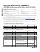
+3.3V SUPPLY AC ELECTRICAL CHARACTERISTICS (continued)
(
Typical Application Circuit,
typical values are at V
CC
= +3.3V, P
RF
= -5dBm, P
LO
= 0dBm, f
RF
= 3550MHz, f
LO
= 3200MHz,
f
IF
= 350MHz, T
C
= +25°C, unless otherwise noted.) (Note 8)
PARAMETER SYMBOL CONDITIONS MIN TYP MAX UNITS
IF Output Impedance Z
IF
Nominal differential impedance at the IC’s
IF outputs
200 Ω
IF Output Return Loss
RF terminated into 50Ω, LO driven by a 50Ω
source, IF transformed to 50Ω using
external components shown in the Typical
Application Circuit
19 dB
RF-to-IF Isolation 28 dB
LO Leakage at RF Port -36 dBm
2LO Leakage at RF Port -34 dBm
LO Leakage at IF Port -27 dBm
Channel Isolation
RFM AIN ( RFD IV ) conver ted p ow er
m easur ed at IFD IV ( IFM AIN ) , r el ati ve to
IFM AIN ( IFD IV ) , al l unused p or ts ter m i nated
to 50Ω
38.5 dB
Note 5: Not production tested.
Note 6: Guaranteed by design and characterization.
Note 7: Operation outside this range is possible, but with degraded performance of some parameters. See the
Typical Operating
Characteristics
section.
Note 8: All limits reflect losses of external components, including a 0.9dB loss at f
IF
= 350MHz due to the 4:1 impedance trans-
former. Output measurements were taken at IF outputs of the
Typical Application Circuit
.
Note 9: 100% production tested for functional performance.
Note 10: Maximum reliable continuous input power applied to the RF or IF port of this device is +12dBm from a 50Ω source.
Note 11: Measured with external LO source noise filtered so the noise floor is -174dBm/Hz. This specification reflects the effects of
all SNR degradations in the mixer, including the LO noise as defined in Application Note 2021:
Specifications and
Measurement of Local Oscillator Noise in Integrated Circuit Base Station Mixers
.