
Owner manual


MAX19996
SiGe High-Linearity, 2000MHz to 3000MHz
Downconversion Mixer with LO Buffer
______________________________________________________________________________________ 15
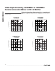
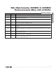
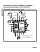
Pin Description
PIN NAME FUNCTION
1, 6, 8, 14 V
CC
Power Supply. Bypass to GND with 0.01µF capacitors as close as possible to the pin.
2RF
Single-Ended 50Ω RF Input. Internally matched and DC shorted to GND through a balun. Requires
an input DC-blocking capacitor.
3, 4, 5, 10,
12, 13, 17
GND
Ground. Internally connected to the exposed pad. Connect all ground pins and the exposed pad
(EP) together.
7 LOBIAS
LO Amplifier Bias Control. Output bias resistor for the LO buffer. Connect a 604Ω 1% resistor
(230mA bias condition) from LOBIAS to ground.
9, 15 N.C. Not internally connected. Pins can be grounded.
11 LO
Local Oscillator Input. This input is internally matched to 50Ω. Requires an input DC-blocking
capacitor.
16 LEXT
External Inductor Connection. Connect an inductor from this pin to ground to increase the RF-to-IF
and LO-to-IF isolation (see the Typical Operating Characteristics for typical performance vs. inductor
value).
18, 19 IF-, IF+
Mixer Differential IF Output. Connect pullup inductors from each of these pins to V
CC
(see the
Typical Application Circuit).
20 IFBIAS
IF Amplifier Bias Control. IF bias resistor connection for the IF amplifier. Connect a 698Ω 1% resistor
(230mA bias condition) from IFBIAS to GND.
—EP
Exposed Pad. Internally connected to GND. Connect to a large ground plane using multiple vias to
maximize thermal and RF performance.