
Instruction Manual


MAX1471
315MHz/434MHz Low-Power, 3V/5V
ASK/FSK Superheterodyne Receiver
8 _______________________________________________________________________________________
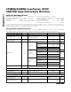
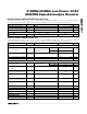
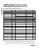
PIN NAME FUNCTION
6 XTAL1 1st Crystal Input
7AV
DD
Analog Power-Supply Voltage for RF Sections. AV
DD
is connected to an on-chip +3.0V low-dropout
regulator. Decouple to AGND with a 0.1µF capacitor.
8 LNAIN Low-Noise Amplifier Input
9 LNASRC
Low-Noise Amplifier Source for External Inductive Degeneration. Connect an inductor to AGND to set
LNA input impedance.
10
LNAOUT
Low-Noise Amplifier Output. Connect to mixer through an LC tank filter.
11 MIXIN+ Differential Mixer Input. Must be AC-coupled to driving input.
12 MIXIN- Differential Mixer Input. Bypass to AGND with a capacitor.
13 MIXOUT 330Ω Mixer Output. Connect to the input of the 10.7MHz IF filter.
14 AGND Analog Ground
15 IFIN- Differential 330Ω IF Limiter Amplifier Input. Bypass to AGND with a capacitor.
16 IFIN+ Differential 330Ω IF Limiter Amplifier Input. Connect to output of the 10.7MHz IF filter.
17 PDMINF Minimum-Level Peak Detector for FSK Data
18
PDMAXF
Maximum-Level Peak Detector for FSK Data
19 DSF- Inverting Data Slicer Input for FSK Data
20 DSF+ Noninverting Data Slicer Input for FSK Data
21 OPF+ Noninverting Op-Amp Input for the FSK Sallen-Key Data Filter
22 DFF Data-Filter Feedback Node. Input for the feedback of the FSK Sallen-Key data filter.
23 DGND Digital Ground
24 DV
DD
Digital Power-Supply Voltage for Digital Sections. Connect to AV
DD
. Decouple to DGND with a 10nF
capacitor.
25 FDATA Digital Baseband FSK Demodulator Data Output
26 CS Active-Low Chip-Select Input
27 DIO Serial Data Input/Output
28 SCLK Serial Interface Clock Input
29 HV
IN
High-Voltage Supply Input. For 3V operation, connect HV
IN
to AV
DD
and DV
DD
.
30 ADATA Digital Baseband ASK Demod Data Output
31 PDMINA Minimum-Level Peak Detector for ASK Output
32
PDMAXA
Maximum-Level Peak Detector for ASK Output
EP GND Exposed Paddle. Connect to ground.
Pin Description (continued)