
User guide


MAX1464
Low-Power, Low-Noise Multichannel
Sensor Signal Processor
40 ______________________________________________________________________________________
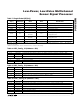
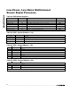
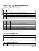
OSC[4:0]
BINARY DECIMAL
% CHANGE FROM NOMINAL
CLOCK FREQUENCY (%)
01111 15 +43.7
01110 14 +42.2
01101 13 +40.1
01100 12 +38.4
01011 11 +35.2
01010 10 +32.8
01001 9 +28.8
01000 8 +25.5
00111 7 +17.7
00110 6 +14.1
00101 5 +10.0
00100 4 +8.4
00011 3 +5.4
00010 2 +3.6
00001 1 +1.4
00000 0 0
11111 -1 -3.4
11110 -2 -4.9
11101 -3 -7.2
11100 -4 -9.1
11011 -5 -12.6
11010 -6 -15.1
11001 -7 -18.5
11000 -8 -21.0
10111 -9 -25.3
10110 -10 -27.2
10101 -11 -29.9
10100 -12 -32.1
10011 -13 -35.8
10010 -14 -38.1
10001 -15 -40.9
10000 -16 -43.0
Table 35. Oscillator Trim Settings
(Two’s Complement)
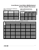
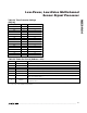
ENCKOUT
CKSEL
(PIN)
CKIO DESCRIPTION
X 0 Input
Internal oscillator is
halted. An external clock
must be supplied to
CKIO pin.
01
High
impedance
Internal oscillator is
running. CKIO output
driver is disabled.
1 1 Output
Internal oscillator is
running. CKIO output
driver is enabled driving
clock output.
Table 36. Internal Oscillator and CKIO
Control
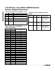
BITS
NAME DESCRIPTION
15–13
— Unused.
12–8
OSC[4:0]
Oscillator trim setting. OSC[4] = MSB.
7–6 — Unused.
5–4 — Reserved 0.
3–1
— Unused.
0
ENCKOUT
Enable clock output: 1 = enable
internal clock output on CKIO based
on CKSEL inputs, 0 = disable.
Table 34. Oscillator Control (Address = 32h)