
User guide


MAX1464
Low-Power, Low-Noise Multichannel
Sensor Signal Processor
_______________________________________________________________________________________ 3
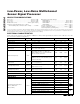
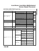
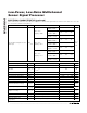
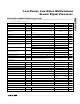
PARAMETER SYMBOL CONDITIONS MIN TYP MAX UNITS
PGA[4:0] = 00000, CLK[2:0] = 000 430
PGA[4:0] = 01010
,
CLK[2:0] = 000 55
PGA[4:0] = 11111, CLK[2:0] = 000 36
kΩ
PGA[4:0] = 00000, CLK[2:0] = 011 3.4 MΩ
PGA[4:0] = 01010, CLK[2:0] = 011 440
PGA[4:0] = 11111, CLK[2:0] = 011 288
kΩ
PGA[4:0] = 00000, CLK[2:0] = 110 27
PGA[4:0] = 01010, CLK[2:0] = 110 3.5
Single-Sided Input Impedance
(INP1 to V
SS
, INM1 to V
SS
,
INP2 to V
SS
, INM2 to V
SS
)
R
SIN
PGA[4:0] = 11111, CLK[2:0] = 110 2.3
MΩ
Common-Mode Rejection Ratio CMRR Common-mode voltage V
CM
= V
SS
to V
DD
0.008 %FS
Differential Signal-Gain Range Selectable in 17 steps (Note 5) 0.99 to 244 V/V
PGA[4:0] = 00000 0.95 0.99 1.05
PGA[4:0] = 00001 7.3 7.7
8.2
PGA[4:0] = 01010 71 77 82
PGA[4:0] = 10100 137 153 168
Differential Signal Gain A
VDIFF
PGA[4:0] = 11110 203 244 283
V/V
Gain-Error Temperature
Coefficient
GETC
ADC
PGA[4:0] = 00000 -8 ppm/°C
COARSE-OFFSET DAC
Resolution 3-bit plus sign 4 Bits
PGA[4:0] =
00000 to 01000
137 147 157
PGA[4:0] =
01010 to 10000
273 291 308
REF = V
DD
,
CO[3:0] = 0111
PGA[4:0] =
10100 to 11110
525 578 630
PGA[4:0] =
00000 to 01000
57 64 69
PGA[4:0] =
01010 to 10000
113 126 136
REF = V
DD
,
CO[3:0] = 0011
PGA[4:0] =
10100 to 11110
228 251 276
PGA[4:0] =
00000 to 01000
-3 -1 +1
PGA[4:0] =
01010 to 10000
-7 -2.4 +2
Effective Offset Adjustment at the
ADC Input
OA
ADC
REF = V
DD
,
CO[3:0] = 0000
PGA[4:0] =
10100 to 11110
-11 -4 +3
% of
ADC
Ref
ELECTRICAL CHARACTERISTICS (continued)
(V
DDF
= V
DD
= 4.5V to 5.5V, V
SSF
= V
SS
= 0V, f
CLK
= 4.0MHz, T
A
= T
MIN
to T
MAX
. Typical values are at V
DDF
= V
DD
= 5.0V, V
SSF
= V
SS
= 0V,
T
A
= +25°C, unless otherwise noted.) (Note 1)