
Manual


MAX11041/MAX11042
Wired Remote Controllers
4 _______________________________________________________________________________________
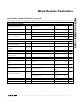
Note 1: Recommended properties of external switch for proper detection of 30 keys or key combinations.
Note 2: See the Jack Insertion/Removal Detection section.
Note 3: C
b
is the bus capacitance in pF.
Note 4: Key current depends on external key resistors and is calculated by V
DD
/ (30.1kΩ + R
SW
).
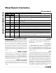
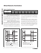
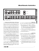
Figure 1. I
2
C Serial-Interface Timing
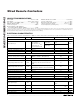
ELECTRICAL CHARACTERISTICS (continued)
(V
DD
= +1.6V to 3.6V, C
SENSE
= 10nF, R
SENSE
= 10kΩ, T
A
= T
MIN
to T
MAX
, unless otherwise noted. Typical values are at T
A
= +25°C.)
PARAMETER SYMBOL CONDITIONS MIN TYP MAX UNITS
POWER SUPPLIES
Power-Supply Voltage V
DD
1.6 3.6 V
Excluding jack/key current 5 20
Average Operational Supply
Current
I
DDOP
Jack inserted, R
JACK
= 619kΩ 8
µA
Shutdown Power-Supply Current I
DDSHDN
Excluding jack/key current 1 µA
Jack Current I
DDJACK
Flowing when jack is inserted 4 µA
Key Current I
DDBUTTON
Flowing when keys pressed (Note 4) 90 µA
SHDN High to Part Active Wake-up time 5 ms
t
HD,STA
t
SU,DAT
SDA
t
HD,DAT
SCL
STOP CONDITION
(P)
t
SU,STA
t
SU,STO
t
LOW
t
BUF
START CONDITION
(S)
t
HD,STA
t
HIGH
t
RR,
t
RT
t
FR,tFT
t
RR
t
FR
START CONDITION
(S)
REPEAT START CONDITION
(Sr)