
User guide

ISD5100 – SERIES
Publication Release Date: October, 2003
- 51 - Revision 0.2
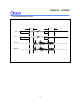
ACAP (AGC Capacitor)
This pin provides the capacitor connection for setting the parameters of the microphone AGC circuit. It
should have a 4.7 µF capacitor connected to ground. It cannot be left floating. This is because the
capacitor is also used in the playback mode for the AutoMute circuit. This circuit reduces the amount
of noise present in the output during quiet pauses. Tying this pin to ground gives maximum gain; tying
it to V
CCA
gives minimum gain for the AGC amplifier but cancels the AutoMute function.
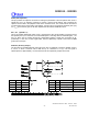
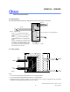
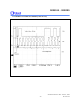
SP +, SP- (Speaker +/-)
This is the speaker differential output circuit. It is designed to drive an 8 speaker connected across
the speaker pins up to a maximum of 23.5 mW RMS power. This stage has two selectable gains, 1.32
and 1.6, which can be chosen through the configuration registers. These pins are biased to ap-
proximately 1.2 VDC and, if used single-ended, must be capacitively coupled to their load. Do NOT
ground the unused pin.
AUX OUT (Auxiliary Output)
The AUX OUT is an additional audio output pin to be used, for example, to drive the speaker circuit in
a “car kit.” It drives a minimum load of 5k and up to a maximum of 1V p-p. The AC signal is
superimposed on approximately 1.2 VDC bias and must be capacitively coupled to the load.
Speak er
SP+
SP–
AUX OUT
Car Kit
(1 Vp-p Max)
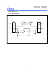
ANA IN AMP
OUT PUT
MUX
FILTO
SUM2
2
VO L
(OPS1,OPS0)
2
(OPA1, OPA0)
INS0
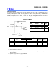
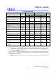
15 14 13 12 11 10 9 8 7 6 5 4 3 2 1 0
AIG1 AIG0 AIPD AXG1 AXG0 AXPD AOS2 AOS1 AOS 0 AOPD OP S1 OPS0 OP A1 OPA0 VL PD
CFG0
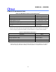
OPS1 OPS0 SOURCE
0 0 VOL
0 1 ANA IN
1 0 FILTO
1 1 SUM2
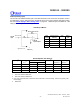
OPS1 OPA0 SPKR DRIVE AUX OUT
0 0 Power Down Power Down
0 1 3.6 V
p.p
@150Ω Power Down
1 0 23.5 mWatt @ 8Ω Power Down
1 1 Power Down 1 V
p.p
Max @ 5KΩ