
User guide


ISD5100 – SERIES
- 14 -
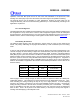
Note that the processor could have sent an I
2
C STOP
after the Status Word data transfer and aborted the
transfer of the Address bytes.
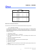
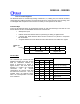
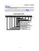
A graphical representation of this operation is found
below. See the caption box above for more
explanation.
S SLAVE ADDRESS
A
A
DATA P
R
DATADATA
A
N
Status
Hi
g
h Addr.
Low Addr.
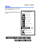
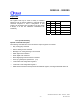
Conventions used in I
2
C Data
Transfer Diagrams
= START Condition
= STOP Condition
= 8-bit data transfer
= “1” in the R/W bit
= “0” in the R/W bit
= ACK (Acknowledge)
= No ACK
S
SLAVE ADDRESS
A
DATA
P
= Host to Slave (Gray)
=
Slave to Host (White)
The Box color indicates the direction
of data flow
= 7-bit Slave
Address
N
R
W