
Manual


ISD4004 Series
7
ISD
SPI PORT
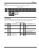
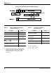
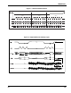
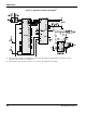
The following diagram describes the SPI port and the control bits associated with it.
Figure 3: SPI Port
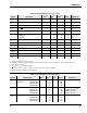
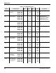
SPI CONTROL REGISTER
The SPI control register provides control of individual device functions such as Play, Record, Message
Cueing, Power-Up and Power-Down, Start and Stop operations, and Ignore Address pointers.
Table 3: SPI Control Register
Control
Register
Bit Device Function
Control
Register
Bit Device Function
RUN Enable or Disable an operation PU Master power control
=
=
1
0
Start
Stop
=
=
1
0
Power-Up
Power-Down
P/R Selects Play or Record operation IAB Ignore address control bit
=
=
1
0
Play
Record
=
=
1
0
Ignore input address register (A15–A0)
Use the input address register contents
for an operation (A15–A0)
MC Enable or Disable Message Cueing P15–P0 Output of the row pointer register
=
=
1
0
Enable Message Cueing
Disable Message Cueing
A15–A0 Input address register