
Manual


ISD2100 DATASHEET
Publication Release Feb 9, 2010
- 7 - Revision 0.51
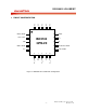
6
SPI INTERFACE
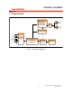
This is a standard four-wire interface used for communication between ISD2100 and the host. It
consists of an active low slave-select (SSB), a serial clock (SCLK), a data input (Master Out Slave In -
MOSI), and a data output (Master In Slave Out - MISO). In addition, for some transactions requiring
data flow control, a RDY/BSYB signal (pin) is available.
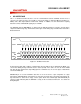
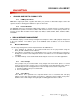
The ISD2100 supports SPI mode 3: (1) SCLK must be high when SPI bus is inactive, and (2) data is
sampled at SCLK rising edge. A SPI transaction begins on the falling edge of SSB and its waveform is
illustrated below:
0 1 2 3 4 5 6 7 0 1
2 3 4 5 6 7
SSB
SCLK
MISO
MOSI
XC7 C6 C5X C4 C3 C2 C1 C0
S7 S6 S5 S4 S3 S2 S1 S0 D7 D6 D5 D4 D3 D2 D1 D0
D7 D6 D5 D4 D3 D2 D1 D0
Z X
Figure 6-1 SPI Data Transaction.
A transaction begins with sending a command byte (C7-C0) with the most significant bit (MSB – C7)
sent in first. During the byte transmission, the status (S7-S0) of the device is sent out via the MISO
pin. After the byte transmission, depending upon the command sent, one or more bytes of data will be
sent via the MISO pin.
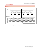
RDY/BSYB pin is used to handshake data into or out of the device. Upon completion of a byte
transmission, RDY/BSYB pin could change its state after the rising edge of the SCLK if the built-in 32-
byte data buffer is either full or empty. At this point, SCLK must remain high until RDY/BSYB pin
returns to high, indicating that the ISD2100 is ready for the next data transmission. See below for
timing diagram.