
Instruction Manual

ISD1916
Publication Release Date: September 11, 2007
- 8 - Revision 0
PIN NAME PIN # I / O FUNCTION
MIC- 19 I
MIC- : Inverting input of the differential microphone signal. While
FT
is enabled,
MIC- pin is disabled and must be floated.
Rosc 20 I
Oscillator Resistor: Connect an external resistor from this pin to V
SSA
to select the
internal sampling frequency.
V
CCA
21 I
Analog Power Supply: Power supply for analog circuits.
LED
22 O
LED output: During recording, this output is Low. Also, LED pulses Low
momentarily at the end of playback.
PLAYE / FMC2
23 I
PLAYE : In Norm mode, low active input, edge-trigger playback from start to end
addresses & toggle on-off. Debounce & internal pull-up existed.
FMC2 : When MODE is active, FMC2 , together with FMC1 & FMC3 , setup
various fixed-message configurations.
REC / /PR
24 I
REC : In Norm mode, level-hold (after 1 sec holding) or edge-trigger (toggle on-off),
low active, recording from start to end addresses. Debounce & internal pull-up
existed.
/PR ( When MODE is active):
• When /PR is set to Low, level-hold record operation is selected.
• When
/PR is set to High, edge-trigger & toggle on-off playback operation is
selected.
XCLK / FMC3
25 I
External Clock:
In Norm mode, low active and level-hold input. As XCLK
activated, Rosc pin accepts external clock input signal, provided resistor at Rosc
must be removed. Connecting this pin to High enables device running on internal
clock via Rosc resistor. If not used, XCLK must be at high level.
When MODE is active, FMC3 , together with FMC1 & FMC2 , setup various fixed-
message configurations.
FT
26 I
Feed-Through : Low active input, Level-hold, debounce & Internal pull-up required.
When
FT is selected, the MIC+ input is configured to a single-ended input with
1Vp-p maximum input amplitude and feed-through to the speaker outputs.
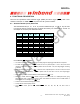
Norm / MODE
27 I Level-hold input.
• Norm : When set to High, the device operates under Address trigger condition.
•
MODE : When set to Low, the device operates under direct trigger condition. The
device reconfigures its pin definitions to fit various fixed-message configurations
utilizing
FMC1
,
FMC2
& FMC3 pins as below table.
FMC3
FMC2 FMC1
# of fixed messages
0 0 0 1
0 0 1 2
0 1 0 3
0 1 1 4
1 0 0 5
1 0 1 6
1 1 0 7
1 1 1 8
V
CCD
28 I
Digital Power Supply: Power supply for digital circuits.
Notes:
[1]
: Address bits S0 , S1 , S2 , S3 , E0 , E1 , E2 & E3 are used to access the memory location.