
Instruction Manual

ISD1916
Publication Release Date: September 11, 2007
- 7 - Revision 0
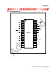
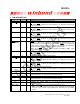
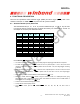
5. PIN DESCRIPTION
PIN NAME PIN # I / O FUNCTION
V
SSD
1 I
Digital Ground: Ground path for digital circuits.
S0 /
M1
2 I
S0
[1
]
: In Norm mode, Start Address Bit 0.
M1 : When MODE is active, low active operation on 1
st
Message. Internal pull-up
& debounce existed.
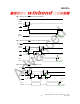
S1 /
M2
3 I
S1
[1
]
: In Norm mode, Start Address Bit 1.
M2 : When MODE is active, low active operation on 2
nd
Message. Internal pull-up
& debounce existed.
S2 / M3
4 I
S2
[1
]
: In Norm mode, Start Address Bit 2.
M3 : When MODE is active, low active operation on 3
rd
Message. Internal pull-up
& debounce existed.
S3 / M4
5 I
S3
[1
]
: In Norm mode, Start Address Bit 3.
M4 : When MODE is active, low active operation on 4
th
Message. Internal pull-up
& debounce existed.
PLAYL / FMC1
6 I
PLAYL : In Norm mode, low active input, Level-hold playback start to end
addresses, debounce & internal pull-up existed. Holding
PLAYL Low constantly will
perform looping playback function from start to end addresses with insignificant
dead time between messages regardless of sampling frequencies.
FMC1 : When MODE is active, FMC1 , together with FMC2 & FMC3 , setup
various fixed-message configurations.
E0 / M5
7 I
E0
[1
]
: In Norm mode, End Address Bit 0.
M5 : When MODE is active, low active operation on 5
th
Message. Internal pull-up
& debounce existed.
V
SSA
8 I
Analog Ground: Ground path for analog circuits.
E1
/ M6
9 I
E1
[1
]
: In Norm mode, End Address Bit 1.
M6 : When MODE is active, low active operation on 6
th
Message. Internal pull-up
& debounce existed.
E2 / M7
10 I
E2
[1
]
: In Norm mode, End Address Bit 2.
M7 : When MODE is active, low active operation on 7
th
Message. Internal pull-up
& debounce existed.
E3 / M8
11 I
E3
[1
]
: In Norm mode, End Address Bit 3.
M8
: When
MODE
is active, low active operation on 8
th
Message. Internal pull-up
& debounce existed.
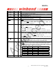
V
SSP2
12 I
Ground: Ground for negative PWM speaker driver.
SP- 13 O
SP-: Negative signal of the differential Class-D PWM speaker outputs. This output,
together with the SP+, is used to drive an 8Ω speaker directly.
V
CCP
14 I
Speaker Power Supply: Power supply for PWM speaker drivers.
SP+ 15 O
SP+: Positive signal of the differential Class-D PWM speaker outputs. This output,
together with the SP-, is used to drive an 8Ω speaker directly.
V
SSP1
16 I
Ground: Ground for positive PWM speaker driver.
AGC 17 I
Automatic Gain Control (AGC): The AGC adjusts the gain of the microphone
preamplifier circuitry.
MIC+ / AnaIn 18 I
• MIC+ : Non-inverting input of the differential microphone signal.
• AnaIn : When
FT is selected, the MIC+ input is configured to a single-ended
input with 1Vp-p maximum input amplitude and feed-through to the speaker
outputs.