
Manual


ISD1600B SERIES
Publication Release Date: Jan. 23, 2007
- 15 - Revision 1.2
9. ELECTRICAL CHARACTERISTICS
9.1. DC PARAMETERS
PARAMETER SYMBOL MIN TYP
[1]
MAX UNITS CONDITIONS
Supply Voltage V
DD
2.4 5.5 V
Input Low Voltage V
IL
V
SS
-0.3 0.3xV
DD
V
Input High Voltage V
IH
0.7xV
DD
V
DD
V
Output Low Voltage V
OL
V
SS
-0.3 0.3xV
DD
V I
OL
= 4.0 mA
[2]
Output High Voltage V
OH
0.7xV
DD
V
DD
V I
OH
= -1.6 mA
[2]
Record Current I
DD_Record
20 mA
Playback Current I
DD_Playback
20 mA
V
DD
= 5.5V, No load,
Sampling freq = 12 kHz
Standby Current I
SB
1 10 µA
[3] [4]
Input Leakage Current I
ILPD1
±1
µA Force V
DD
[5]
Input Current HIGH I
ILPD2
-3 -10 µA Force V
SS
[5]
Preamp Input Resistance R
MIC+,
R
MIC-
20 K Across both pins
MIC Input Voltage V
IN
15 300 mV Peak-to-Peak
[6]
Gain from MIC to SP+/- A
MSP
6 40 dB V
IN
= 15 to 300mV,
AGC = 4.7µF,
V
DD
= 2.4V to 5.5V
Output Load Impedance R
EXT
8 Speaker Load
670 mW
V
DD
= 5.5V
313 mW
V
DD
= 4.4V
117 mW
V
DD
= 3V
Speaker Output Power Pout
49 mW
V
DD
= 2.4V
15mVp-p
1kHz freq
sinewave,
R
EXT
= 8;
Speaker Output Voltage Vout V
DD
V
R
EXT
= 8 (Speaker),
typical buzzer
AUD I
AUD
-3.0 mA V
DD
=4.5V, R
EXT
= 390
Total Harmonic Distortion THD 1 %
15mV p-p 1KHz sinewave,
Cmessage weighted
Notes:
[1]
Conditions: V
CC
= 4.5V, 8kHz sampling frequency and T
A
= 25°C, unless otherwise stated.
[2]
LED output during Record operation.
[3]
V
CCA,
V
CCD
and V
CCP
are connected together. V
SSA
, V
SSP
and V
SSD
are connected together.
[4]
REC
, PLAYE and PLAYL must be at V
CCD
.
[5]
REC
,
PLAYE
and
PLAYL
are forced to specified condition.
[6]
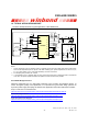
Balanced input signal applied between MIC and MIC REF as shown in the applications example. Single-
ended MIC or MIC REF recommended to be less than 100 mV peak to peak.