
Manual

ISD14B20
Publication Release Date: October 9, 2007
- 8 - Revision 0
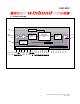
5. FUNCTIONAL DESCRIPTION
There are two operational modes: address trigger ( ) and direct trigger (
NORM
MODE
). After a new
condition is selected on /
NORM
MODE
, the power must be cycled to enable it.
5.1. ADDRESS TRIGGER ( ) OPERATION
NORM
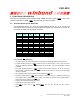
The start address bits ( , , & ) and end address bits ( , , & ) are used
to access the memory location and they can divide the memory into a maximum of 16 slots. As
an example of I14B20, they are defined as follows:
S0 S1 S2 S3 E0 E1 E2 E3
S3
( )
E3
S2
( )
E2
S1
(
E1
)
S0
(
E0
)
Row # 14B20
Duration [s]
0 0 0 0 0 0
0 0 0 1 8 1.25
0 0 1 0 16 2.50
0 0 1 1 24 3.75
0 1 0 0 32 5.00
0 1 0 1 40 6.25
0 1 1 0 48 7.50
0 1 1 1 56 8.75
1 0 0 0 64 10.00
1 0 0 1 72 11.25
1 0 1 0 80 12.50
1 0 1 1 88 13.75
1 1 0 0 96 15.00
1 1 0 1 104 16.25
1 1 1 0 112 17.50
1 1 1 1 120 18.75
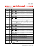
5.1.1. Record (
REC
) Operation
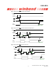
• Low active input, level-hold for level-trigger or falling edge for edge-trigger with debounce required.
• For 8kHz sampling frequency, if
REC
is held at Low for a period equal to 1 sec or more, then level
recording is activated. However, if
REC
is pulsed Low for less than 1 sec, then edge-trigger recording
is initiated.
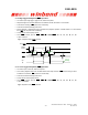
• For 6.4kHz sampling frequency, if
REC
is held at Low for a period equal to 1.25 sec or more, then
level recording is activated. However, if
REC
is pulsed Low for less than 1.25 sec, then edge-trigger
recording is initiated.
• Recording begins from the start address to end address and
LED
is on.
• Recording ceases whenever
REC
returns to High in level-hold mode or a subsequent lower going
pulse appears while in edge-trigger mode or when end address is reached. Then an EOM marker is
written at the end of message. And
LED
is off.
• Then the device will automatically power down.
• This pin has an internal pull-up device.
• Once
REC
is active, input on
FT
, /
NORM
MODE
, , , , , , , or is
illegal.
S0 S1 S2 S3 E0
E1 E2
E3