
User Manual


HD44780U
37
Power Supply for Liquid Crystal Display Drive
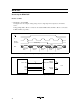
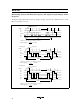
Various voltage levels must be applied to pins V1 to V5 of the HD44780U to obtain the liquid crystal
display drive waveforms. The voltages must be changed according to the duty factor (Table 10).
VLCD is the peak value for the liquid crystal display drive waveforms, and resistance dividing provides
voltages V1 to V5 (Figure 21).
Table 10 Duty Factor and Power Supply for Liquid Crystal Display Drive
Duty Factor
1/8, 1/11 1/16
Bias
Power Supply 1/4 1/5
V1 V
CC
–1/4 VLCD V
CC
–1/5 VLCD
V2 V
CC
–1/2 VLCD V
CC
–2/5 VLCD
V3 V
CC
–1/2 VLCD V
CC
–3/5 VLCD
V4 V
CC
–3/4 VLCD V
CC
–4/5 VLCD
V5 V
CC
–VLCD V
CC
–VLCD
V
CC
V1
V4
V5
V2
V3
V
CC
V1
V2
V3
V4
V5
R
R
R
R
VR
–5 V
V
CC
(+5 V)
–5 V
V
CC
(+5 V)
R
R
R
R
R
VR
VLCDVLCD
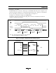
1/4 bias
(1/8, 1/11 duty cycle)
1/5 bias
(1/16, duty cycle)
Figure 21 Drive Voltage Supply Example