
User Manual


GM862-QUAD / PY Hardware User Guide
1vv0300748 Rev. 5 - 20/09/07
Reproduction forbidden without Telit Communications S.p.A. written authorization - All Rights Reserved page 61 of 68
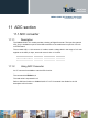
11 ADC section
11.1 ADC converter
11.1.1 Description
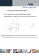
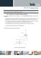
The GM862-QUAD / PY module provides a Analog to Digital Converter. The input line (named
ADC_IN1) is available on pin #6 of the B2B connector of the module and on pin #19 of PL103
on EVK2 Board.
The on board A/D is 11-bit converter. It is able to read a voltage level in the range of 0÷2 volts
applied on the ADC pin input, store and convert it into 11 bit word.
Min Max Units
Input Voltage range 0 2 Volt
AD conversion - 11 bits
Resolution - < 1 mV
11.1.2 Using ADC Converter
An AT command is available to use the ADC function.
The command is AT#ADC=1,2
The read value is expressed in mV
Refer to SW User Guide or to GM862-QUAD / PY AT Commands User Guide for the full
description of this function.