
User Manual


GM862-QUAD / PY Hardware User Guide
1vv0300748 Rev. 5 - 20/09/07
Reproduction forbidden without Telit Communications S.p.A. written authorization - All Rights Reserved page 47 of 68
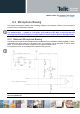
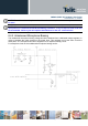
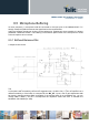
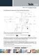
8.5.2 Buffered Unbalanced (Single Ended) Microphone
The above schematic can be used for a single ended (buffered unbalanced) microphone; the required
biasing circuitry is not included. Note also that the capacitor C3 is not needed.
The gains of the two amplifiers are given by the formulas:
()
720
719
1buffer invertingnot
R
R
Gain +=
()
708
711
buffer inverting
R
R
Gain =
Assigning half of overall gain to each amplifier, you will obtain the requested gain because of doubling
the microphone signal path; in fact by the use of two amplifiers (the upper as “inverting” and the lower
as “not inverting” configuration ) we obtain an additional +6dB gain (2 times) .
Remember: the “not inverting“ amplifier section gain shall not be less than 1 .
Like for the balanced buffered microphone, the amplifier overall gain can be modify changing the value
of resistor R719/R720 and R711 and as a consequence the capacitors C726 and C727. It is
advisable to change R708 only if you have difficulty to find a commercial value for R711; in this case
change R708 as little as possible.
The -3dB bandwidth is given by the approximated formula (considering C725 >> C726):
727*711*2
1
726*719*2
1
.
CRCR
freq
ππ
==
[Hz]
2,7nF
6,8nF