
User Manual

GM862-QUAD / PY Hardware User Guide
1vv0300748 Rev. 5 - 20/09/07
Reproduction forbidden without Telit Communications S.p.A. written authorization - All Rights Reserved page 38 of 68
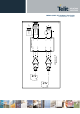
8.1 Microphone Paths Characteristic and
Requirements
TIP: being the microphone circuitry the more noise sensitive, its design and layout must be
done with particular care. Both microphone paths are balanced and the OEM circuitry should
be balanced designed to reduce the common mode noise typically generated on the ground
plane. However also an unbalanced circuitry can be used for particular OEM application needs.
TIP: due to the difference in the echo canceller type, the “Mic_MT” audio path is suited for
Handset applications, while the “Mic_HF”audio path is suited for hands-free function (car kit).
The Earphone applications should be made using the “Mic_HF” audio path but DISABLING the
echo canceller by software AT command. If the echo canceller is left active with the Earphone,
then some echo might be introduced by the echo cancel algorithm.
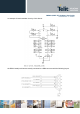
“Mic_MT” 1
st
differential microphone path
• line coupling AC (*)
• line type balanced
• coupling capacitor ≥ 100nF
• differential input resistance 50kΩ
• max differential input voltage 1,03V
pp
(365mV
rms
)/@MicG=0
• microphone nominal sensitivity -45 dBV
rms
/Pa
• analog g
ain suggested + 20dB
• echo canceller type handset
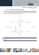
“Mic_HF” 2
nd
differential microphone path
• line coupling AC (*)
• line type balanced
• coupling capacitor ≥ 100nF
• differential input resistance 50kΩ
• max differential input voltage 1,03V
pp
(365mV
rms
)
@
MicG=0
• microphone nominal sensitivity -45 dBV
rms
/Pa
• analog
gain suggested +10dB
• echo canceller type car kit hands-free