
User Manual


GM862-QUAD / PY Hardware User Guide
1vv0300748 Rev. 5 - 20/09/07
Reproduction forbidden without Telit Communications S.p.A. written authorization - All Rights Reserved page 24 of 68
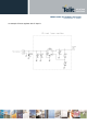
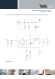
6.2.1.2 + 12V input Source Power Supply Design Guidelines
• The desired output for the power supply is 3.8V, hence due to the big difference between the input
source and the desired output, a linear regulator is not suited and shall not be used. A switching
power supply will be preferable because of its better efficiency especially with the 2A peak current
load represented by the GM862-QUAD / PY.
• When using a switching regulator, a 500Khz switching frequency regulator is preferable because
of its smaller inductor size and its faster transient response. This allows the regulator to respond
quickly to the current peaks absorption.
• In any case the frequency and Switching design selection is related to the application to be
developed due to the fact the switching frequency could also generate EMC interferences.
• For car PB battery the input voltage can rise up to 15,8V and this should be kept in mind when
choosing components: all components in the power supply must withstand this voltage.
• A Bypass low ESR capacitor of adequate capacity must be provided in order to cut the current
absorption peaks, a 100μF tantalum capacitor is usually suited.
• Make sure the low ESR capacitor on the power supply output (usually a tantalum one) is rated at
least 10V.
• For Car applications a spike protection diode should be inserted close to the power input, in order
to clean the supply from spikes.
• A protection diode should be inserted close to the power input, in order to save the GM862-QUAD
/ PY from power polarity inversion. This can be the same diode as for spike protection.