
User Manual


GM862-QUAD / PY Hardware User Guide
1vv0300748 Rev. 5 - 20/09/07
Reproduction forbidden without Telit Communications S.p.A. written authorization - All Rights Reserved page 14 of 68
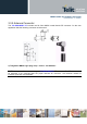
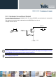
4.2 GSM Antenna - Installation Guidelines
• Install the antenna in a place covered by the GSM signal.
• The Antenna must be installed to provide a separation distance of at least 20 cm from all persons
and must not be co-located or operating in conjunction with any other antenna or transmitter;
• Antenna shall not be installed inside metal cases
• Antenna shall be installed also according Antenna manufacturer instructions.
4.3 Logic level specifications
Where not specifically stated, all the interface circuits work at 2.8V CMOS logic levels. The following
table shows the logic level specifications used in the Telit GM862-QUAD/PY interface circuits:
Absolute Maximum Ratings -Not Functional
Parameter Min Max
Input level on any
digital pin when on
-0.3V +3.6V
Input voltage on
analog pins when on
-0.3V +3.0 V
Voltage on Buffered
pins
-0.3V 25V
Operating Range - Interface levels (2.8V CMOS)
Level Min Max
Input high level 2.1V 3.3V
Input low level 0V 0.5V
Output high level 2.2V 3.0V
Output low level 0V 0.35V
For 2,0V signals:
Operating Range - Interface levels (2.0V CMOS)
Level Min Max
Input high level 1.6V 3.3V
Input low level 0V 0.4V
Output high level 1,65V 2.2V
Output low level 0V 0.35V