
User guide


Confidential, the whole present document is the sole property of Maestro Wireless
Solution Limited.
5
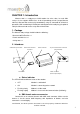
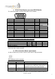
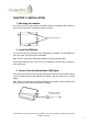
c. 15-Pin D-Sub Female connector (RS232/Audio)
The connector provides serial link and audio link to the modem
Pin number Name EIA designation Type Note
1 DCD Data Carrier Detect Output
2 TX Transmit Data Input
3 BOOT Input Not used
4 MICROPHONE (+) Input
5 MICROPHONE (-) Input
With 2VDC bias
output
6 RX Receive Data Output
7 DSR Data Set Ready Output
8 DTR Data Terminal Ready
Input
9 GND Ground Ground
10 SPEAKER (+) Output
11 CTS Clear To Send Output
12 RTS Request To Send Input
13 RI Ring Indicator Output
14 RESET Input Pull low to reset
15 SPEAKER (-) Output
Specification of microphone and speaker to be connected:
Parameters Min Typical
Max Remark
Microphone current @2V/2K Ohm 0.5mA
Microphone input level 100 mVpp
Speaker output current 150 Ohm/1nF 16mA
Speaker impedance 32ohm 50Ohm
Please refer to the document "Application notes - Power supply & Audio" for more
information about audio connection.
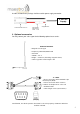
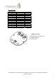
d. 4-Pin connector (Power input/output)
A cable, included in the package shall be used for power supply connection:
Pin assignment of 4-Pin connector
Pin number Name Functions
1 I/O Input/Output port
2 ~INTR Interrupt function triggered by pulling this
pin to ground or LOW level; reserved for
additional functions with new firmware
3 POWER - DC power negative input
4 POWER + DC power positive input