
Manual
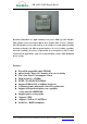

EB-A803-P GPS Engine Board
EverMore Technology, Inc.
2F, No.7, R&D Road 1, Science-Based Industrial Park, Hsinchu, Taiwan, 300, R.O.C. http://www.emt.com.tw
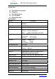
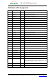
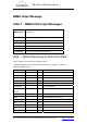
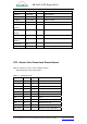
Definition of Pin assignment
Pin# Name Type Description
1
VCC I DC Supply Voltage Input DC +3.3V+-5%
2
GND G Digital Reference Ground
3
VDD18 O Internal regulator output, 1.8V
4
RXA I Serial Port A, 5V > V
IH
> 1.46V, V
IL
< 0.41V
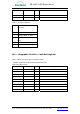
5
TXA O Serial Port A, V
OH
> 2.8V, V
OL
< 0.4V
6
TXB O Serial Port B, V
OH
> 2.8V, V
OL
< 0.4V
7
RXB I Serial Port B, 5V > V
IH
> 1.46V, V
IL
< 0.41V
8
GPSMODE12 I GPSMODE12 configuration (reserved, keep floating)
9
RF_ON O Indicates power state of RF part, 3.3V
10
GND G Digital Reference Ground
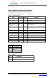
11~15
GND_A G Analog Reference Ground
16
GND_A G Analog Reference Ground
17
RF_IN I GPS Signal Input, 50 ohm @1.57542GHz
18
GND_A G Analog Reference Ground
19
V_ANT_IN I Active Antenna Bias Voltage
20
VCC_RF O Supply Active Antenna Bias Voltage, 3.3VDC typical
21
V_BAT I Backup Voltage Supply, 1.5VDC~ 3.6VDC
22
NRESET I Reset, Active Low, V
IL
< 0.41V
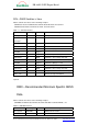
23
GPSMODE2 I GPSMODE2 configuration (reserved, keep floating)
24
GPSMODE5 I Serial I/O configuration (reserved, keep floating)
25
GPSMODE6 I Serial I/O configuration (reserved, keep floating)
26
USB_DM I/O USB DM
27
USB_DP I/O USB DP
28
STATUS_LED O GPS Fix Status Indicator. When GPS is not fixed, it
outputs low. When GPS is fixed, it outputs pulse. (see
figure 1.), V
OH
> 2.8V, V
OL
< 0.4V
29
PPS O One Pulse Per Second, V
OH
> 2.8V, V
OL
< 0.4V
30
GND G Digital Reference Ground