
Manual
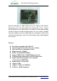


EB-A802-P GPS Engine Board
EverMore Technology, Inc.
2F, No.7, R&D Road 1, Science-Based Industrial Park, Hsinchu, Taiwan, 300, R.O.C. http://www.emt.com.tw
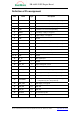
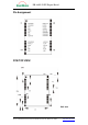
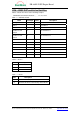
Definition of Pin assignment
Pin# Name Type Description
1
GPSMODE8 I Antenna detection configuration, keep floating
2
GPSMODE9 I Antenna detection configuration, keep floating
3
TxD1 O Serial Port 1, if not used keep floating
4
RxD1 I Serial Port 1, if not used keep floating
5
VDDIO I Pad voltage supply, 3.3V typical
6
VCC I Supply voltage, 3.3V typical
7
GND I Ground
8
VDD18OUT O Internal 1.8V regulator output, if not used keep floating
9
GPSMODE10 I Antenna detection configuration, keep floating
10
RESET_N I Reset Pin, active low, if not used keep floating
11
V_BAT I 1.5V~ 3.6V Input for backup RTC&SRAM
12
NC Not Connected, keep floating
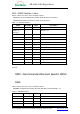
13~15
GND I Ground
16
RF_IN I GPS signal input
17
GND I Ground
18
VCC_RF O Output Voltage RF section
19
V_ANT I Antenna Bias voltage
20
AADET_N I Active Antenna Detect (see application circuit)
21
GPSMODE3 I Sensitivity mode configuration, keep floating
22
GPSMODE2 I Sensitivity mode configuration, keep floating
23
GPSMODE7 I
USB Power Mode configuration, keep floating (Default
is self-powered) (“0” is bus-powered)
24
VDD_USB I USB Supply, 3.3V typical
25
USB_DM I/O USB data
26
USB_DP I/O USB data
27
EXTINT0 I External Interrupt Pin
28
TIMEPULSE O Time pulse (1 PPS)