
Manual


DS31256
63 of 181
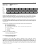
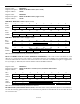
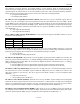
Repetitive Pattern Length Map
Length Code Length Code Length Code Length Code
17 Bits 0000 18 Bits 0001 19 Bits 0010 20 Bits 0011
21 Bits 0100 22 Bits 0101 23 Bits 0110 24 Bits 0111
25 Bits 1000 26 Bits 1001 27 Bits 1010 28 Bits 1011
29 Bits 1100 30 Bits 1101 31 Bits 1101 32 Bits 1111
Bit 13/Interrupt Enable for Counter Overflow (IEOF). Allows the receive BERT to cause an interrupt if either
the bit counter or the error counter overflows.
0 = interrupt masked
1 = interrupt enabled
Bit 14/Interrupt Enable for Bit Error Detected (IEBED). Allows the receive BERT to cause an interrupt if a bit
error is detected.
0 = interrupt masked
1 = interrupt enabled
Bit 15/Interrupt Enable for Change-of-Synchronization Status (IESYNC). Allows the receive BERT to cause
an interrupt if there is a change of state in the synchronization status (i.e., the receive BERT either goes into or out
of synchronization).
0 = interrupt masked
1 = interrupt enabled
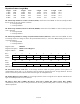
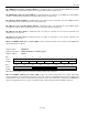
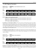
Register Name: BERTC1
Register Description: BERT Control Register 1
Register Address: 0504h
Bit # 7 6 5 4 3 2 1 0
Name EIB2 EIB1 EIB0 SBE n/a n/a
n/a TC
Default 0 0 0 0 0 0 0 0
Bit # 15 14 13 12 11 10 9 8
Name Alternating Word Count
Default 0 0 0 0 0 0 0 0
Note: Bits that are underlined are read-only; all other bits are read-write.
Bit 0/Transmit Pattern Load (TC). A low-to-high transition loads the pattern generator with repetitive or
pseudorandom pattern that is to be generated. This bit should be toggled from low to high whenever the host
wishes to load a new pattern. Must be cleared and set again for subsequent loads.
Bit 4/Single Bit-Error Insert (SBE). A low-to-high transition creates a single bit error. Must be cleared and set
again for a subsequent bit error to be inserted.
Bit 5/Error Insert Bit 0 (EIB0); Bit 6/Error Insert Bit 1 (EIB1); Bit 7/Error Insert Bit 2 (EIB2).
Automatically inserts bit errors at the prescribed rate into the generated data pattern. Useful for verifying error
detection operation.