
Manual


DS31256
36 of 181
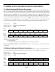
Figure 5-1. Status Register Block Diagram for SM and SV54
Port I/F # 0
#1
#2
#3
#13
#14
#15
#1
#2
#3
#13
#14
#15
OR OR
Receive
OR
SR
COFA
ST
COFA
SBERT
PSERRPPERR
n/an/a
LBINT LBE
RP0CR
Bit #14
RCOFA
Port I/F # 0
Transmit
TP0CR
Bit #14
TCOFA
BERTEC0 Bit 1 (BECO)
BERTEC0 Bit 2 (BBCO)
BERTC0 Bit 13 (IEOF)
Change in BERTEC0 Bit 0 (SYNC)
BERTC0 Bit 15 (IESYNC)
BERTEC0 Bit 3 (BED)
BERTC0 Bit 14 (IEBED)
OR
BERT
int_bd
SLBP0SLBP1SLBP2SLBP3SLBP4SLBP5
SLBP13
SLBP15
SLBP14
SM: Status Master Register
SV54: Status for V54 Detector
Port #15
Change in
V.54 Detector
(SLBP)
Port #0
Change in
V.54 Detector
(SLBP)
Port #1
Change in
V.54 Detector
(SLBP)
Port #14
Change in
V.54 Detector
(SLBP)