
Manual


DS31256
177 of 181
15. APPLICATIONS
This section describes some possible applications for the DS31256. There are numerous potential
configurations but only a few are shown. Users are encouraged to contact the factory for support of their
particular application. Email telecom.support@dalsemi.com or visit our website at
www.maxim-ic.com/telecom
for more information.
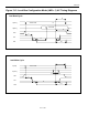
The T1 and E1 channelized application examples in this section are one of two types. The first type is
where a single T1 or E1 data stream is routed to and from the DS31256. This is represented as a thin
arrow in the application examples (Figure 15-1
). Figure 15-2 shows the electrical connections. The
second type consists of four T1 or E1 data streams have been TDM into a single 8.192MHz data stream,
which is routed to and from the DS31256. This type is represented as a thick arrow in Figure 15-1.
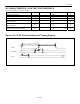
Figure 15-3 shows the electrical connections.
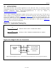
Figure 15-1. Application Drawing Key
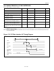
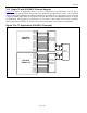
Figure 15-2. Single T1/E1 Line Connection
1
x
SINGLE T1 OR E1 LINE AT 1.544MHz OR 2.048MHz
4
X
QUAD (4) T1 OR 31 LINES BYTE INTERLEAVED AT 8.192MHz
RCLK
RSER
RSYNC
TCLK
TSER
TSYNC
RC
RD
RS
TC
TS
TD
DS31256
ENVOY
DALLAS FRAMER
OR TRANSCEIVER
(ELASTIC STORES
DISABLED)
Note: A looped timed application is shown. The transmit clock may be decoupled from the receive in timing master applications.