
Manual


DS31256
12 of 181
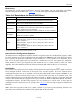
Table 2-B. Initialization Steps
INITIALIZATION STEP COMMENTS
1) Initialize the PCI configuration registers
Achieved by asserting the PIDSEL signal.
2) Initialize all indirect registers
It is recommended that all of the indirect registers be set to
0000h (Table 2-C
).
3) Configure the device for operation
Program all necessary registers, which include the Layer 1,
HDLC, FIFO, and DMA registers.
4) Enable the HDLC channels
Done through the RCHEN and TCHEN bits in the
R[n]CFG[j] and T[n]CFG[j] registers.
5) Load the DMA descriptors
Indicate to the DMA where packet data can be written and
where pending data (if any) resides.
6) Enable the DMAs
Done through the RDE and TDE control bits in the master
configuration (MC) register.
7) Enable DMA for each HDLC channel
Done through the channel enable bit in the receive and
transmit configuration RAM.
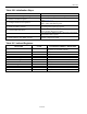
Table 2-C. Indirect Registers
REGISTER NAME NUMBER OF INDIRECT REGISTERS
Channelized Port CP0RD to CP15RD
6144 (16 Ports x 128 DS0 Channels x 3
Registers for each DS0 Channel)
Receive HDLC Channel Definition RHCD 256 (one for each HDLC Channel)
Transmit HDLC Channel Definition THCD 256 (one for each HDLC Channel)
Receive DMA Configuration RDMAC 1536 (one for each HDLC Channel)
Transmit DMA Configuration TDMAC 3072 (one for each HDLC Channel)
Receive FIFO Staring Block Pointer RFSBP 256 (one for each HDLC Channel)
Receive FIFO Block Pointer RFBP 1024 (one for each FIFO Block)
Receive FIFO High Watermark RFHWM 256 (one for each HDLC Channel)
Transmit FIFO Staring Block Pointer TFSBP 256 (one for each HDLC Channel)
Transmit FIFO Block Pointer TFBP 1024 (one for each FIFO Block)
Transmit FIFO Low Watermark TFLWM 256 (one for each HDLC Channel)