
User Manual

DS28DG02: 2kb SPI EEPROM with PIO, RTC, Reset, Battery Monitor, and Watchdog
8 of 33
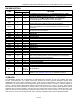
DETAILED REGISTER DESCRIPTIONS
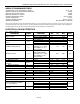
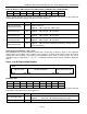
Power-On Default for PIO Output State
ADDR b7 b6 b5 b4 b3 b2 b1 b0
10Ah
POV7 POV6 POV5 POV4 POV3 POV2 POV1 POV0
10Bh
X X X X POV11 POV10 POV9 POV8
There is general read and write access to these addresses. Factory default: 10Ah: FFh; 10Bh: 0Fh. The contents of
this register are automatically transferred to address 120h/121h when the device powers up.
BIT DESCRIPTION BIT(S) DEFINITION
POVn: PIO Power-On
Default State
—
Power-on default output state of PIO0 to PIO11. POV0 applies to PIO0,
etc.
X: (Not Assigned) — Reserved for future use.
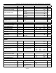
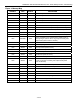
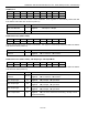
Power-On Default for PIO Direction
ADDR b7 b6 b5 b4 b3 b2 b1 b0
10Ch
POD7 POD6 POD5 POD4 POD3 POD2 POD1 POD0
10Dh
X X X X POD11 POD10 POD9 POD8
There is general read and write access to these addresses. Factory default: 10Ch: FFh; 10Dh: 0Fh. The contents
of this register are automatically transferred to address 122h/123h when the device powers up.
BIT DESCRIPTION BIT(S) DEFINITION
PODn: PIO Power-On
Default Direction
—
Power-on default direction of PIO0 to PIO11. POD0 applies to PIO0, etc.
Legend: 0 Î output; 1 Î input
X: (Not Assigned) — Reserved for future use.
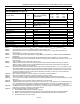
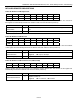
Power-On Default for PIO Read Inversion (PIO0 to PIO7)
ADDR b7 b6 b5 b4 b3 b2 b1 b0
10Eh
PIM7 PIM6 PIM5 PIM4 PIM3 PIM2 PIM1 PIM0
There is general read and write access to this address. Factory default: 00h. The contents of this register are
automatically transferred to address 124h when the device powers up.
BIT DESCRIPTION BIT(S) DEFINITION
PIMn: PIO Power-On
Default Read-Inversion
—
Power-on default state of the read-inversion bit of PIO0 to PIO7. PIM0
applies to PIO0, etc.
Legend: 0 Î no inversion; 1 Î inversion