
Manual

DS26519 16-Port T1/E1/J1 Transceiver
252 of 310
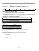
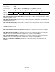
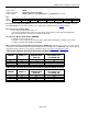
Register Name:
LTIPSR
Register Description:
LIU Transmit Impedance and Pulse Shape Selection Register
Register Address:
1001h + (20h x (n - 1)) + (2000h x [(n - 1) / 8]): where n = 1 to 16
Bit # 7 6 5 4 3 2 1 0
Name TG703 TIMPTON TIMPL1 TIMPL0 — L2 L1 L0
Default 0 0 0 0 0 0 0 0
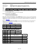
Bit 7: Transmit G.703 Synchronization Clock (TG703)
0 = Normal transmitter mode.
1 = G.703 2.048MHz clock transmitted on TTIPn and TRINGn.
Bit 6: Transmit Impedance On (TIMPTON)
0 = Disable transmit terminating impedance.
1 = Enable transmit terminating impedance.
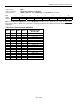
Bits 5 and 4: Transmit Load Impedance 1 and 0 (TIMPL[1:0]). These bits are used to select the transmit load
impedance. These must be set to match the cable impedance. Even if the internal load impedance is turned off (via
TIMPTOFF); the external cable impedance has to be specified for optimum operation. For J1 applications, use
110Ω. See
Table 10-19.
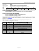
Bits 2 to 0: Line Build-Out Select 2 to 0 (L[2:0])
. Used to select the transmit waveshape. The waveshape has a
voltage level and load impedance associated with it once the T1/J1 or E1 selection is made by settings in the
LTRCR register. See
Table 10-20.
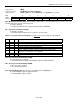
Table 10-19. Transmit Load Impedance Selection
TIMPL1 TIMPLO IMPEDANCE SELECTION
0 0
75Ω
0 1
100Ω
1 0
110Ω
1 1
120Ω
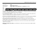
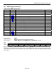
Table 10-20. Transmit Pulse Shape Selection
L2 L1 L0 MODE IMPEDANCE
NOMINAL
VOLTAGE
0 0 0 E1
75Ω
2.37V
0 0 1 E1
120Ω
3.0V
L2 L1 L0 MODE CABLE LENGTH
MAX
ALLOWED
CABLE LOSS
0 0 0 T1/J1
DSX-1/0dB CSU, 0ft–133ft ABAM 100Ω
0.6dB
0 0 1 T1/J1
DSX-1, 133ft–266ft ABAM 100Ω
1.2dB
0 1 0 T1/J1
DSX-1, 266ft–399ft ABAM 100Ω
1.8dB
0 1 1 T1/J1
DSX-1, 399ft–533ft ABAM 100Ω
2.4dB
1 0 0 T1/J1
DSX-1, 533ft–655ft ABAM 100Ω
3.0dB
1 0 1 T1/J1 -7.5dB CSU —
1 1 0 T1/J1 -15dB CSU —
1 1 1 T1/J1 -22.5dB CSU —