
User guide

DS2181A
041995 8/32
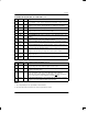
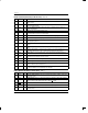
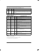
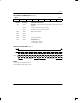
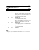
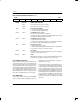
TCR: TRANSMIT CONTROL REGISTER Figure 4
(MSB) (LSB)
TUA1 TSS TSM INBS NBS XBS TSA1 ODM
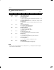
SYMBOL POSITION NAME AND DESCRIPTION
TUA1 TCR.7 Transmit Unframed All 1’s.
0 = Normal operation.
1 = Replace outgoing data at TPOS and TNEG with unframed all 1’s code.
TSS TCR.6 Transmit Signalling Select
1
0 = Signalling data embedded in the serial bit stream is sampled at TSER
during timeslot 16.
1 = Signalling data is channel associated and sampled at TSD as shown in
Table 6.
TSM TCR.5 Transmit Signalling Mode
1
0 = Channel Associated Signalling (CAS).
1 = Common Channel Signalling (CCS).
INBS TCR.4 International Bit Select
0 = Sample international bit at TIND.
1 = Outgoing international bit = TINR.7.
NBS TCR.3 National Bit Select
0 = Sample national bits at TIND.
1 = Source outgoing national bits from TINR.4 through TINR.0.
XBS TCR.2 Extra Bit Select
0 = Sample extra bits at TXD.
1 = Source extra bits from TXR.0 through TXR.1 and TXR.3.
TSA1 TCR.1 Transmit Signalling All 1’s
0 = Normal operation.
1 = Force contents of timeslot 16 in all frames to all 1’s.
ODM TCR.0 Output Data Mode
0 = TPOS and TNEG outputs are 100% duty cycle.
1 = TPOS and TNEG outputs are 50% duty cycle.
NOTE:
1. When the common channel signalling mode is enabled (TCR.5 = 1), the TSD input is disabled internally; all
timeslot 16 data is sampled at TSER.